
Canister mounting structure for motorcycle and motorcycle

a technology for mounting structures and canisters, which is applied in the direction of machines/engines, cycle equipment, combustion air/fuel air treatment, etc., can solve the problems of difficult mounting of canisters

Inactive Publication Date: 2010-04-01
HONDA MOTOR CO LTD
View PDF8 Cites 32 Cited by
  • Summary
  • Abstract
  • Description
  • Claims
  • Application Information

AI Technical Summary

Benefits of technology

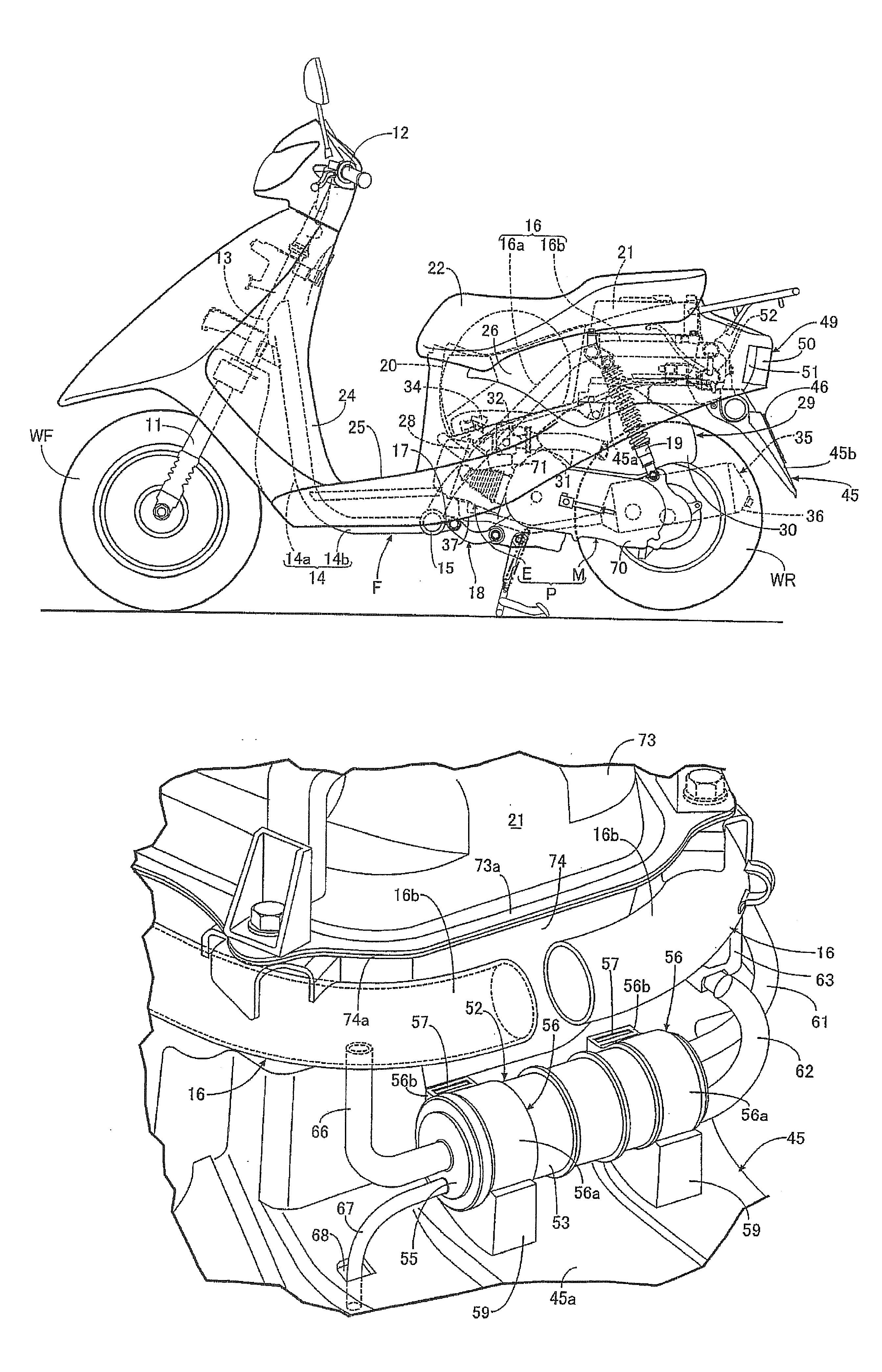
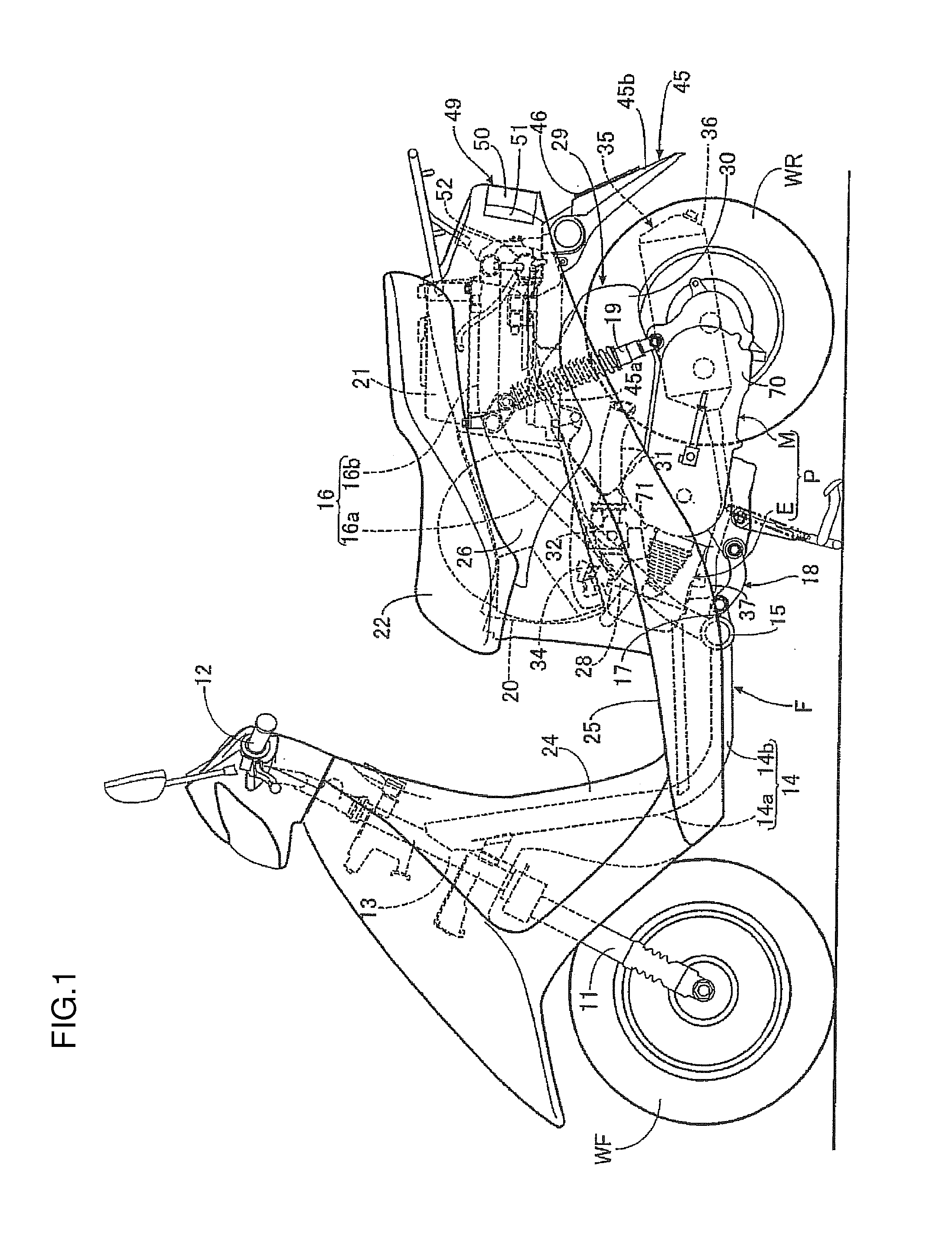
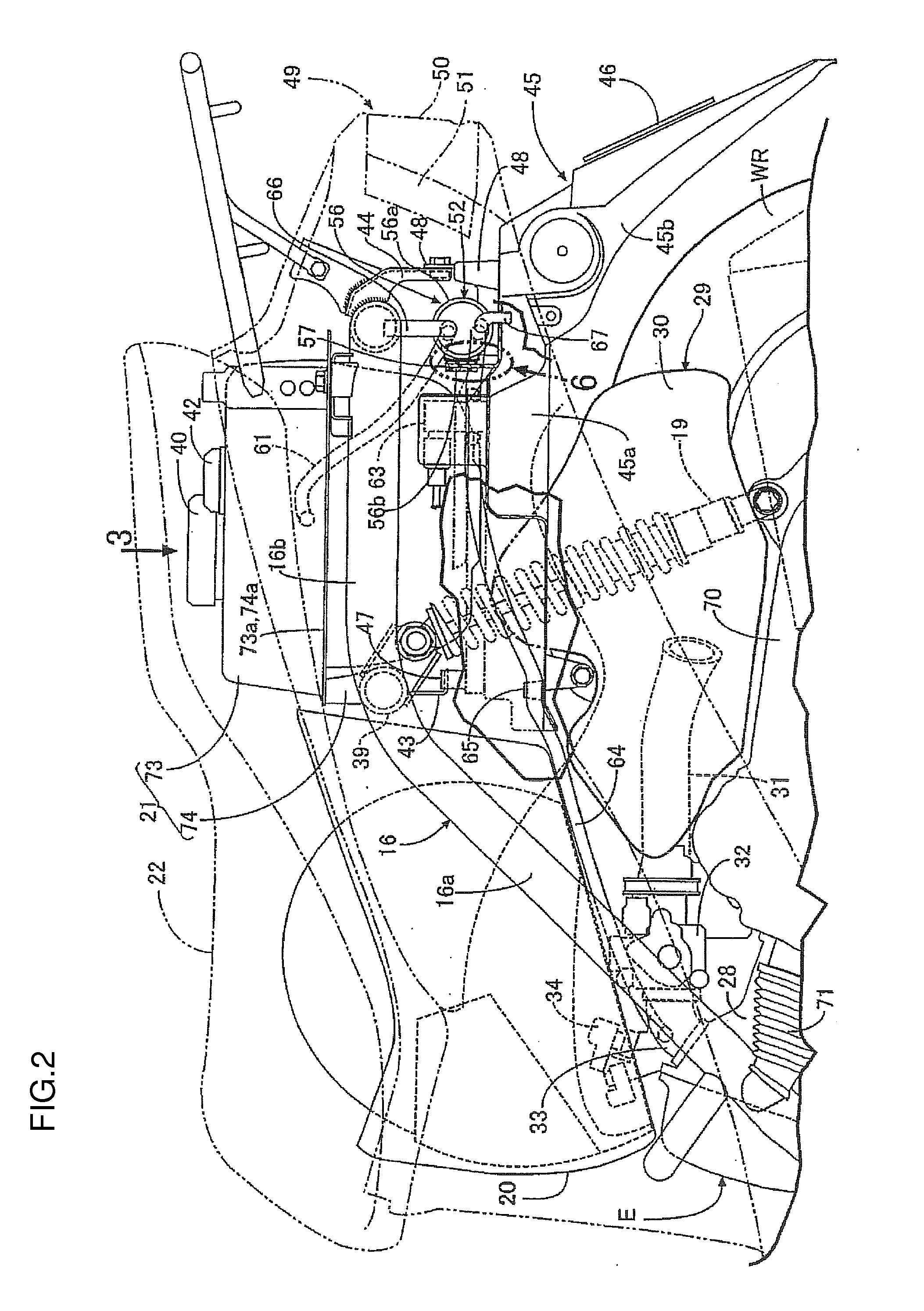
[0054]According to the first embodiment of the present invention, the canister can be fixedly held in position on the rear fender by simply engaging the engagement member disposed on the canister with the lock tab disposed in a protruding condition on the upper surface of the rear fender. These arrangements allow the canister to be mounted on the rear fender through a simple structure and facilitate mounting of the canister.
[0007]According to one aspect of the present invention, a canister mounting structure for a motorcycle includes an engagement member and a lock tab. The engagement member is provided to a canister. The lock tab protrudes from an upper surface of a rear fender supported by a rear portion of a vehicle body frame to cover a rear wheel. The lock tab is engaged with the engagement member so as to hold the canister on the rear fender.
[0056]According to the third embodiment of the present invention, the canister support portion included in the rear fender supports the weight of the canister. This minimizes strength requirements of the engagement portion between the engagement member and the lock tab. In addition, the engagement member, if formed from an elastic material, can inhibit oscillations from being transmitted from the rear fender to the canister.
[0057]According to the fourth embodiment of the present invention, the fuel tank is formed by joining the flange portion of the upper half body and the flange portion of the lower half body. This facilitates molding of the fuel tank. Moreover, the canister is disposed to follow along a wall surface of the lower half body so as to overlap partly the flange portions in a plan view. By disposing the canister in close vicinity to the fuel tank, a charge tube that connects between the fuel tank and the canister can be shortened.
[0058]According to the fifth embodiment of the present invention, the canister is disposed at a position rearward of the fuel tank that is disposed forwardly of the rear stay, and downward of the rear portion of the vehicle body frame and forward of the rear stay. The canister is therefore covered in the fuel tank and the rear stay at the front and rear, respectively, and in the rear portion of the vehicle body frame in the upward direction. The canister can therefore be protected without needing any special protective member.
[0059]According to the sixth embodiment of the present invention, the engagement member or the canister abuts on the rear portion of the vehicle body frame before the engagement member is to slip upwardly out of the lock tab. This eliminates the need for any special lock mechanism that would prevent the engagement member from slipping out of the lock tab, so that the engagement of the engagement member with the lock tab is maintained to hold the canister in place reliably.

Problems solved by technology

This makes it difficult to mount the canister and there is a need for facilitating mounting of the canister.

Method used


Image

  • Canister mounting structure for motorcycle and motorcycle
  • Canister mounting structure for motorcycle and motorcycle
  • Canister mounting structure for motorcycle and motorcycle

Examples


first embodiment

[0047]According to the present invention, there is provided a canister mounting structure for a motorcycle having a rear fender supported by a rear portion of a vehicle body frame, the rear fender for covering a rear wheel from above, and a canister fixedly disposed upwardly of the rear fender. The mounting structure includes an engagement member disposed on the canister and a lock tab disposed in a protruding condition on an upper surface of the rear fender, the engagement member engaging the lock tab so as to hold the canister fixedly on the rear fender.

[0048]According to a second embodiment of the present invention, in addition to the arrangements according to the first embodiment of the present invention, the engagement member is formed from an elastic material to integrate an annular portion that is snapped resiliently over an outer periphery of the canister with an engagement protrusion that protrudes outwardly from the annular portion so as to engage the lock tab.

[0049]Accord...

second embodiment

[0055]According to the present invention, the canister can be easily provided with the engagement member by snapping the annular portion of the engagement member formed from an elastic material resiliently over the outer periphery of the canister. Moreover, engagement of the engagement protrusion of the engagement member with the lock tab is also easy. Oscillations from the lock tab on the side of the rear fender can also be inhibited from being transmitted to the engagement member, specifically, the side of the canister.

third embodiment

[0056]According to the present invention, the canister support portion included in the rear fender supports the weight of the canister. This minimizes strength requirements of the engagement portion between the engagement member and the lock tab. In addition, the engagement member, if formed from an elastic material, can inhibit oscillations from being transmitted from the rear fender to the canister.


PUM


Abstract

A canister mounting structure for a motorcycle includes an engagement member and a lock tab. The engagement member is provided to a canister. The lock tab protrudes from an upper surface of a rear fender supported by a rear portion of a vehicle body frame to cover a rear wheel. The lock tab is engaged with the engagement member so as to hold the canister on the rear fender.

Description

CROSS-REFERENCE TO RELATED APPLICATIONS[0001]The present application claims priority under 35 U.S.C. §119 to Japanese Patent Application No. 2008-251307, filed Sep. 29, 2008. The contents of this application are incorporated herein by reference in their entirety.BACKGROUND OF THE INVENTION[0002]1. Field of the Invention[0003]The present invention relates a canister mounting structure for a motorcycle and a motorcycle.[0004]2. Discussion of the Background[0005]A known motorcycle as disclosed in Japanese Patent Laid-open No. Hei 4-353257 has a rear fender supported on a rear frame at a rear portion of a vehicle body frame and a canister fixedly disposed on the rear fender.[0006]The arrangement disclosed in Japanese Patent Laid-open No. Hei 4-353257, however, has a bracket fixed to the rear frame and the canister mounted on the bracket so as to hang from the rear frame. This makes it difficult to mount the canister and there is a need for facilitating mounting of the canister.SUMMARY O...

Claims


Application Information

Patent Timeline
Patent Type & Authority Applications(United States)
IPC IPC(8): B60K13/02B62K11/00
CPCB60K13/02B62K2202/00B62J37/00B60Y2200/126
Inventor MAEDA, TETSUAKIKOMAKI, AKIRAISHIKAWA, AKIKOMINOWA, KAZUYAKITAMOTO, HIROSHI
Owner HONDA MOTOR CO LTD
Learn More