
Bit-error rate tester with pattern generation

a tester and pattern technology, applied in error detection/correction, digital transmission, instruments, etc., can solve problems such as more susceptible to corruption of patterns

Inactive Publication Date: 2010-03-25
APPLE INC
View PDF9 Cites 11 Cited by
  • Summary
  • Abstract
  • Description
  • Claims
  • Application Information

AI Technical Summary

Problems solved by technology

However, such a pattern is more susceptible to corruption than a more random pattern.

Method used


Image

  • Bit-error rate tester with pattern generation
  • Bit-error rate tester with pattern generation
  • Bit-error rate tester with pattern generation

Examples


Embodiment Construction

[0015]A peripheral component may be designed to communicate with its host processor using a serial protocol may be tested by a testing apparatus operating under that protocol. In the embodiments described herein, the Mobile Industry Processor Interface (MIPI) protocol, administered by the Mobile Industry Processor Interface Alliance, is an example of such a serial protocol.

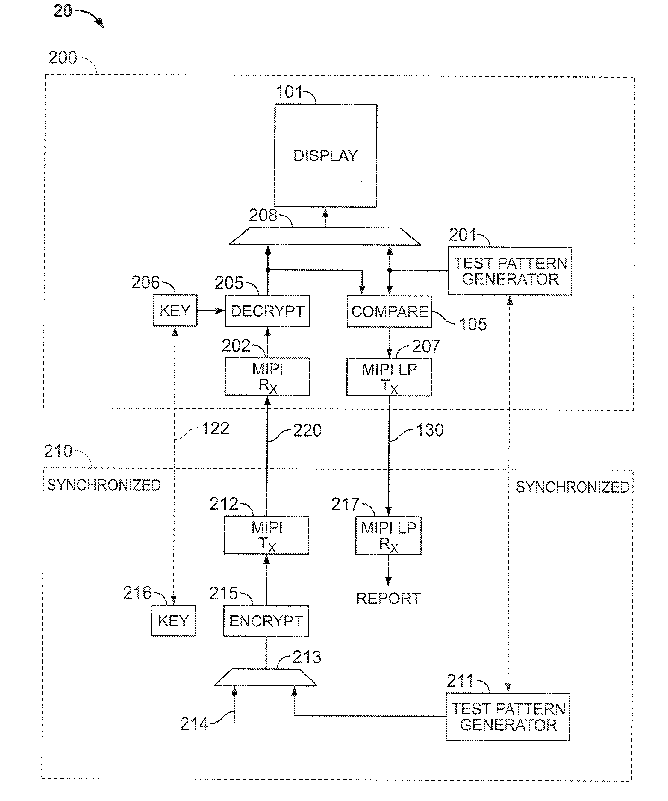
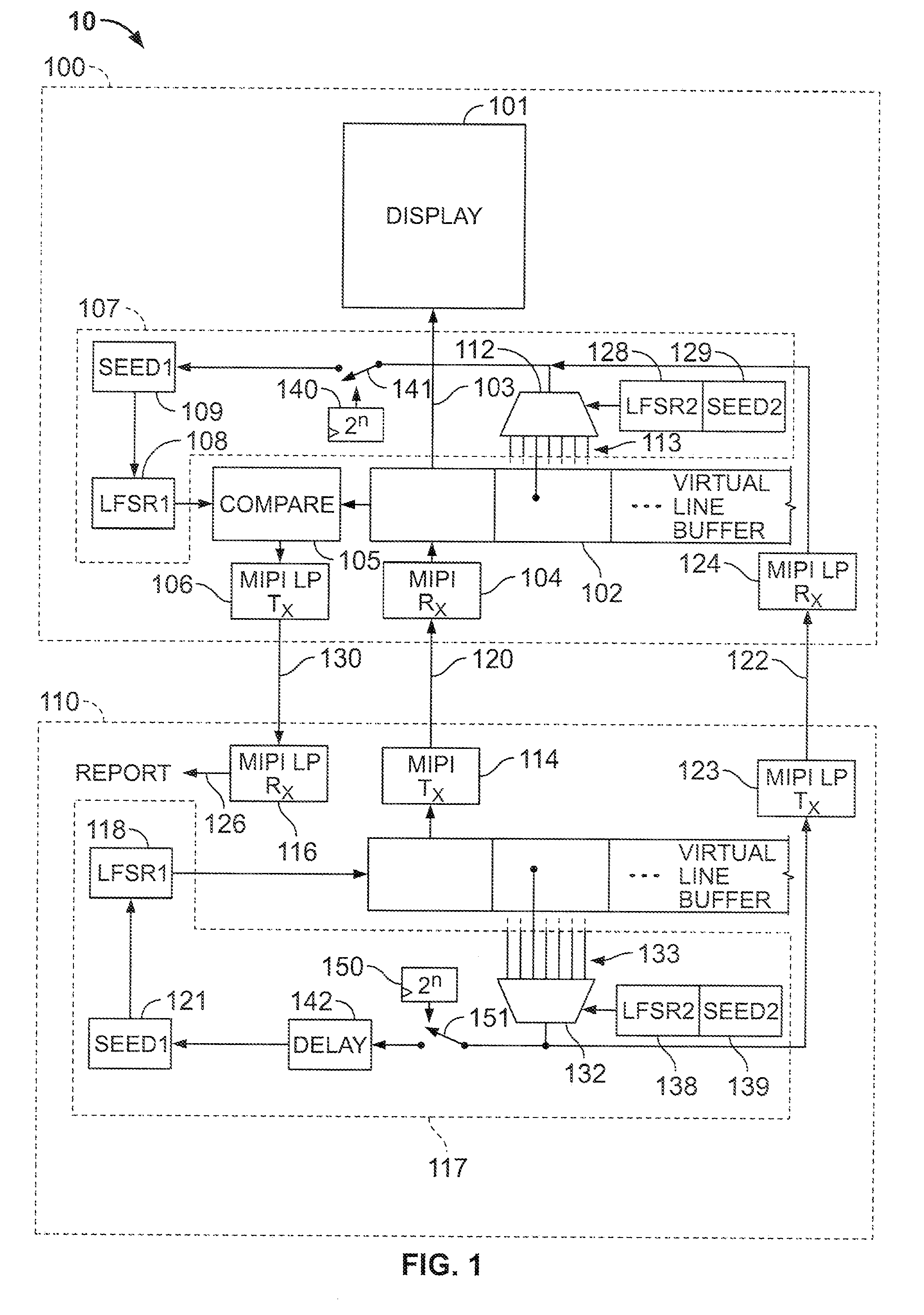
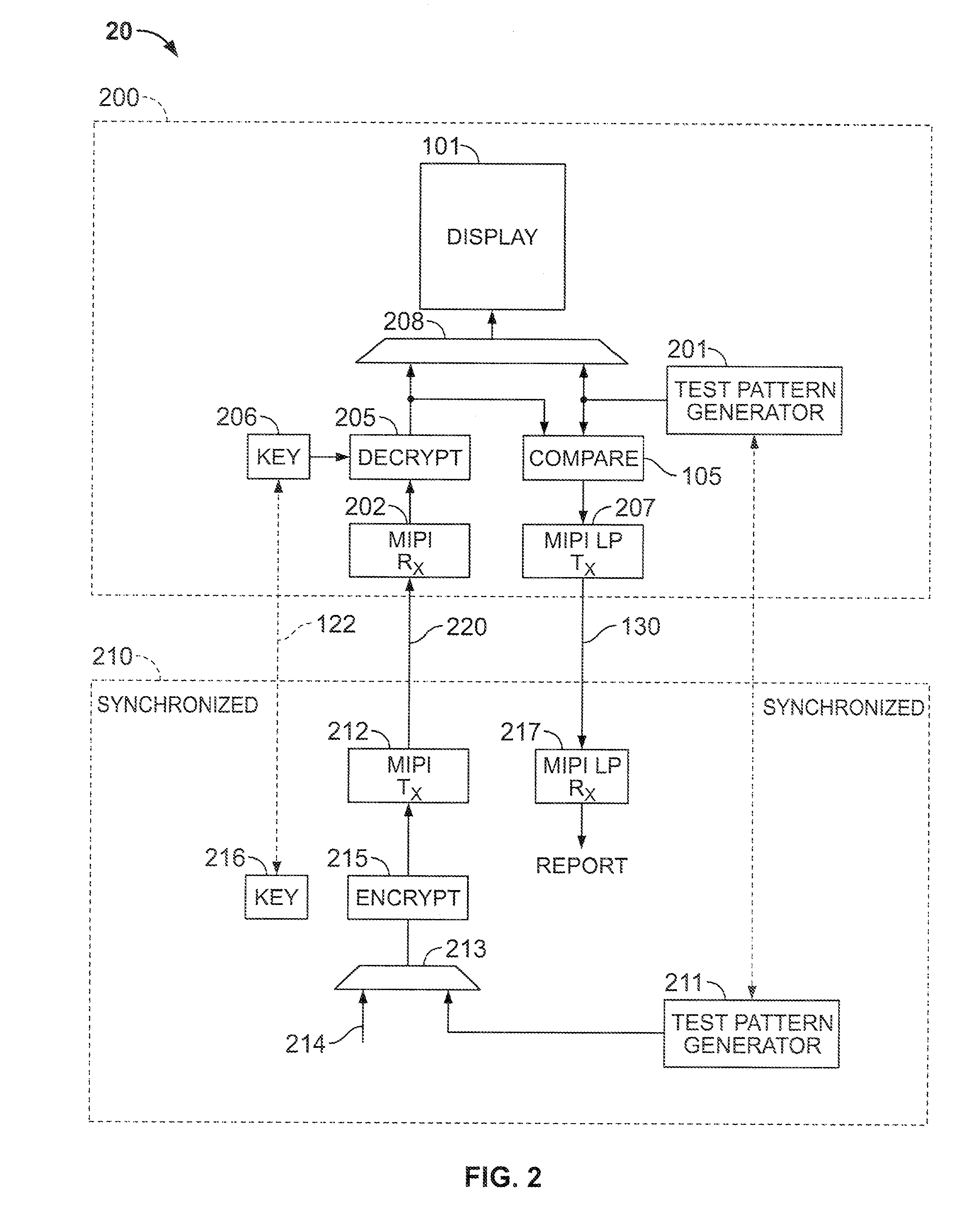
[0016]The invention may be described with reference to FIGS. 1-2, which describe, as an example, the testing, using the MIPI protocol, of a display module (e.g., a liquid-crystal display (LCD) module) used in a portable device that operates under the MIPI protocol. It will be recognized, however, that references to an LCD module and to the MIPI protocol are exemplary only.

[0017]As seen in FIG. 1, in one embodiment of a testing system 10 according to the invention device 100 includes testing circuitry to test display module 101, which may be an LCD panel. Device 100 includes, in addition to display module 101, a pr...


PUM


Abstract

Identical random, or pseudorandom, test patterns in a peripheral device (“receiver”) to be tested, and in a transmitter that sends the test pattern to the receiver, are generated by using pattern generation circuitry in both the transmitter and the receiver that operates identically based on a pattern input value, or seed. The same seed is input to both the transmitter and the receiver. The pattern generation circuitry can be a linear-feedback shift register (“LFSR”), which generates pseudorandom numbers, and identical LFSRs in both the transmitter and the receiver are provided with the same seed. The LFSR may be reseeded periodically. The new seed can be an output of the LFSR itself, or a second LFSR is provided whose output is used to determine the new seed for the first LFSR. Alternatively, cryptographic modules are used in the transmitter and the receiver to generate the test pattern based on identical keys.

Description

CROSS REFERENCE TO RELATED APPLICATION [0001]This claims the benefit of copending, commonly-assigned U.S. Provisional Patent Application No. 61 / 099,848, filed Sep. 24, 2008, which is hereby incorporated by reference herein in its entirety.BACKGROUND OF THE INVENTION [0002]This relates to the testing of a peripheral device associated with an electronic device.[0003]Many kinds of portable electronic devices include processors or systems-on-a-chip (SOCs) that communicate with peripheral components such as memory, displays, or various transducers. In the assembly of such electronic devices, the various components normally will have been tested individually in advance, but it is nevertheless important to test the communications between the components of the assembled devices.[0004]Such testing normally includes the transmission of a test pattern to the peripheral device. The peripheral device compares the pattern as received to the known pattern it is expecting to receive, to determine t...

Claims


Application Information

Patent Timeline
Patent Type & Authority Applications(United States)
IPC IPC(8): G06F11/26H04L9/32
CPCG06F11/263H04L9/12H04L2209/26H04L9/0877H04L9/0662
Inventor LEE, YONGMAN
Owner APPLE INC
Learn More