
Water Level Measuring Apparatus and Measuring Method

a technology of water level and measuring apparatus, applied in the direction of liquid/fluent solid measurement, machines/engines, instruments, etc., can solve the problems of difficult determination, noticeable changes in undesirable situations, and fluctuation of water level up and down, and achieve the effect of smooth fluctuation of obtained water level

Active Publication Date: 2010-03-25
NGK SPARK PLUG CO LTD +1
View PDF2 Cites 0 Cited by
  • Summary
  • Abstract
  • Description
  • Claims
  • Application Information

AI Technical Summary

Benefits of technology

The present invention provides a water level measuring apparatus and method using a filter with a time constant greater than one second to smooth fluctuations in water levels caused by sloshing of the surface. This results in a more accurate water level measurement, even when the surface is in motion. The technique involves applying a filter to a water level signal from a water level indicator and outputting the filtered water level signal as the final water level. This reduces the impact of liquid sloshing and improves the accuracy of water level measurement.

Problems solved by technology

However, in the conventionally proposed water level measuring apparatus, when the surface is stable, the water level can be accurately measured, but when the surface is sloshing, the water level fluctuates up and down, and it is very difficult to determine which fluctuating value should be adopted as the water level.
Particularly, when the water level of a liquid such as fuel carried in a moving vehicle is to be measured, multi-directional acceleration acts on the liquid so that the surface sloshes irregularly, and hence this undesirable situation may appear noticeably.

Method used


Image

  • Water Level Measuring Apparatus and Measuring Method
  • Water Level Measuring Apparatus and Measuring Method
  • Water Level Measuring Apparatus and Measuring Method

Examples


first embodiment

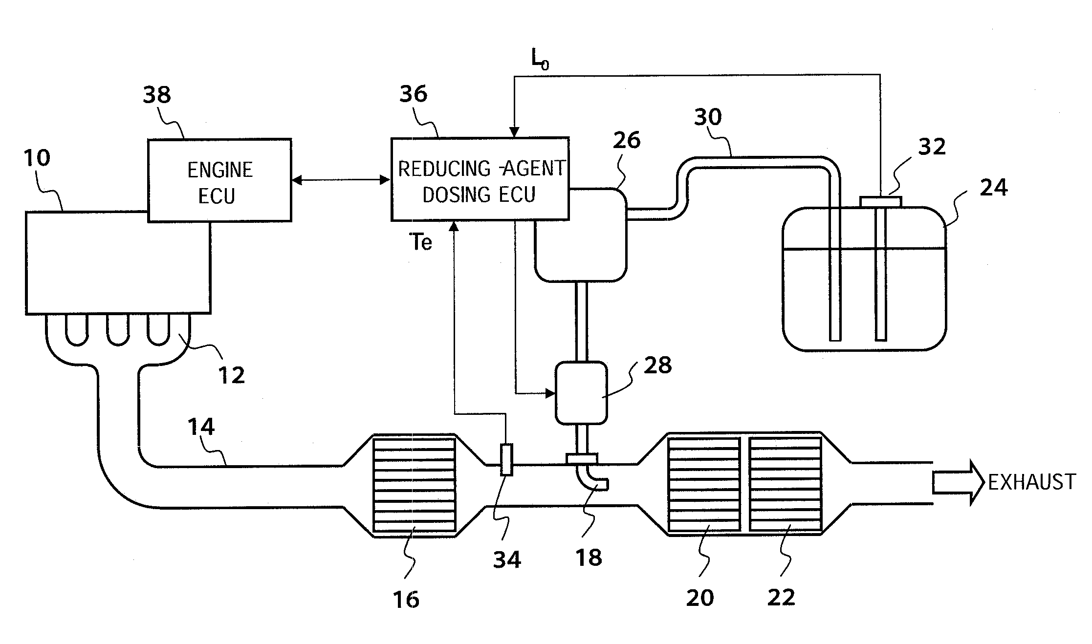
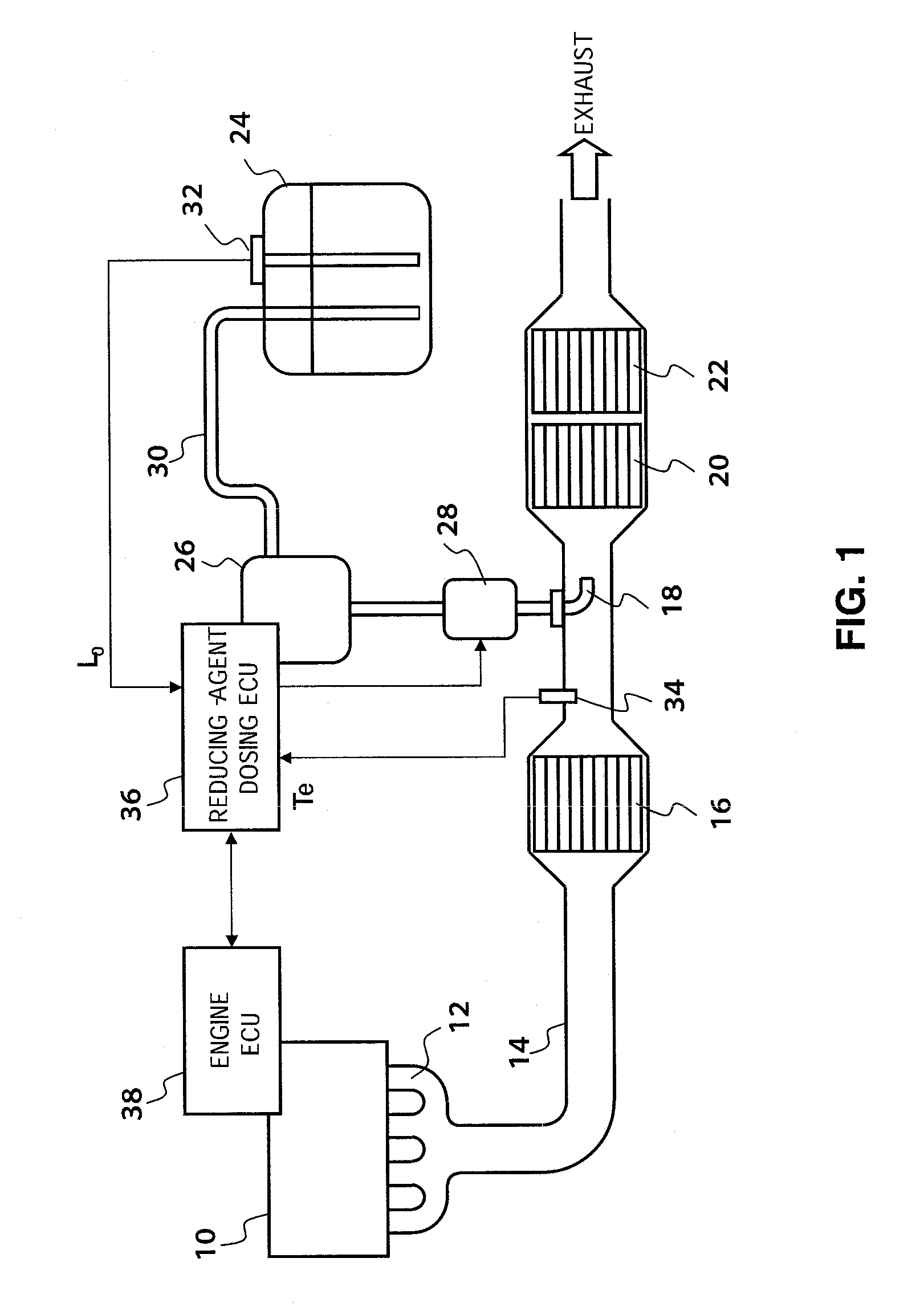
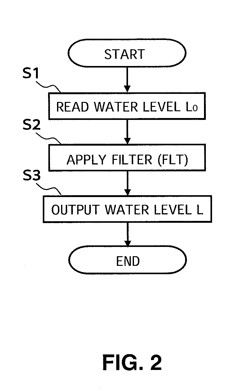
[0020]FIG. 2 shows a control program that is executed repeatedly for each predetermined time period, by the reducing-agent dosing ECU 36.

[0021]In step 1 (abbreviated to “S1” in the figure, and similarly hereunder), the water level L0 is read from the water level indicator 32.

[0022]In step 2, a filter value FLT is calculated by applying a filter with a time constant greater than one second (for example, several hundreds of seconds) to the water level L0.

[0023]In step 3, the filter value FLT is output as the final water level L.

[0024]According to such a water level measuring apparatus, the filter value FLT obtained by applying the filter with a time constant greater than one second to the water level L0 measured by the water level indicator 32, is output as the final water level L. Therefore, as shown in FIG. 3, even if the surface of the urea aqueous solution sloshes so that the water level L0 fluctuates up and down, the fluctuation is smoothed by the filter. Hence there is little in...

second embodiment

[0025]FIG. 4 shows a control program that is executed repeatedly for each predetermined time period, by the reducing-agent dosing ECU 36.

[0026]In step 11, the water level L0 is read from the water level indicator 32.

[0027]In step 12, a filter value FLT is calculated by applying a filter with a time constant greater than one second (for example, several hundreds of seconds) to the water level L0.

[0028]In step 13, a control value representing the injection flow rate of the urea aqueous solution is sequentially integrated according to an equation of “Integrated amount Sum =integrated amount Sum+control value”.

[0029]In step 14, considering that the filter value FLT may include an error caused by a response delay, a correction amount Cor for correcting this is calculated. Specifically, a filter with a time constant greater than one second (for example, several hundreds of seconds) is applied to a moving average of a predetermined number of control values so as to correct the response del...


PUM


Abstract

A water level measuring apparatus and a water level measuring method, in which a water level L0 of a liquid is read from a water level indicator secured to a liquid tank, and a filter value FLT is calculated by applying a filter with a time constant greater than one second to the water level L0, and the filter value FLT is output as a final water level L. Accordingly, even if the surface sloshes and the water level L0 fluctuates up and down, the water level L0 is smoothed by the filter. Hence there is little influence of the liquid sloshing, and the water level measurement accuracy can be improved.

Description

CROSS-REFERENCE TO RELATED APPLICATIONS[0001]This application is a continuation of PCT / JP2007 / 067600, filed on Sep. 10, 2007, and entitled “Water Level Measuring Device and Water Level Measuring Method,” which claims priority to Japanese Patent Application No. 2006-260055, filed on Sep. 26, 2006, the disclosures of which are incorporated herein by reference in their entirety.FIELD OF THE INVENTION[0002]The present invention relates to a technique for measuring a water level highly accurately, even if sloshing occurs in a liquid stored in a liquid tank.BACKGROUND OF THE INVENTION[0003]As a water level measuring apparatus that measures the water level of a liquid stored in a liquid tank, there has been proposed a technique for indirectly measuring the water level based on a change in an interelectrode capacitance of a pair of electrodes arranged with a predetermined gap therebetween, as disclosed in Japanese Laid-Open (Kokai) Patent Application Publication No. H11(1999)-311561. Moreov...

Claims


Application Information

Patent Timeline
Patent Type & Authority Applications(United States)
IPC IPC(8): G01F23/00
CPCG01F25/0061G01F23/0069G01F23/802G01F25/20
Inventor MATSUNAGA, HIDEKIKUMAZAWA, SHINJIMOTOMURA, MASAYUKIYAZAWA, KATSUNORI
Owner NGK SPARK PLUG CO LTD
Learn More