
Neutralization apparatus

a technology of neutralizer and eliminator, which is applied in the direction of electrostatic charge, electrical apparatus, corona discharge, etc., can solve the problems of uneven air flow speed, dielectric effect, and elevated surface electric potential of work, so as to eliminate static electricity and effectively and effectively perform the effect of eliminating static electricity

Active Publication Date: 2010-03-25
SMC CORP
View PDF11 Cites 14 Cited by
  • Summary
  • Abstract
  • Description
  • Claims
  • Application Information

AI Technical Summary

Benefits of technology

[0015]According to the static eliminator of the present invention described above in detail, elimination of static electricity from a work can be effectively and surly performed. Further, elimination of static electricity can be performed without furiously elevating the electric potential of the work surface even the static eliminator is placed at a close distance to the work.

Problems solved by technology

However, the static eliminator using a pulse DC system generates a large amount of ions, so that when the static eliminator is placed at a close distance (for example, not more than 100 mm) to a work which is a target for eliminating static electricity, an instantaneous surface electric potential of the work may be adversely elevated up to near 500 V with respect to the target 0 V as a large amount of ions are discharged to the work.
In addition, a high voltage is applied to a discharge needle in pulse, so that when the static eliminator is placed at a close distance to a work, there is a problem in that the surface electric potential of the work is elevated by the dielectric effect of the discharge needle.
Further, ionized air is directly ejected toward a work from a nozzle in the conventional static eliminator, so that there is a problem in that unevenness of air flow speed, distribution unevenness of ions, or the like occurs between a position at which the nozzle exists and a position at which the nozzle does not exist and elimination of static electricity from a work is difficult to be uniformly performed.

Method used


Image

  • Neutralization apparatus
  • Neutralization apparatus
  • Neutralization apparatus

Examples


Embodiment Construction

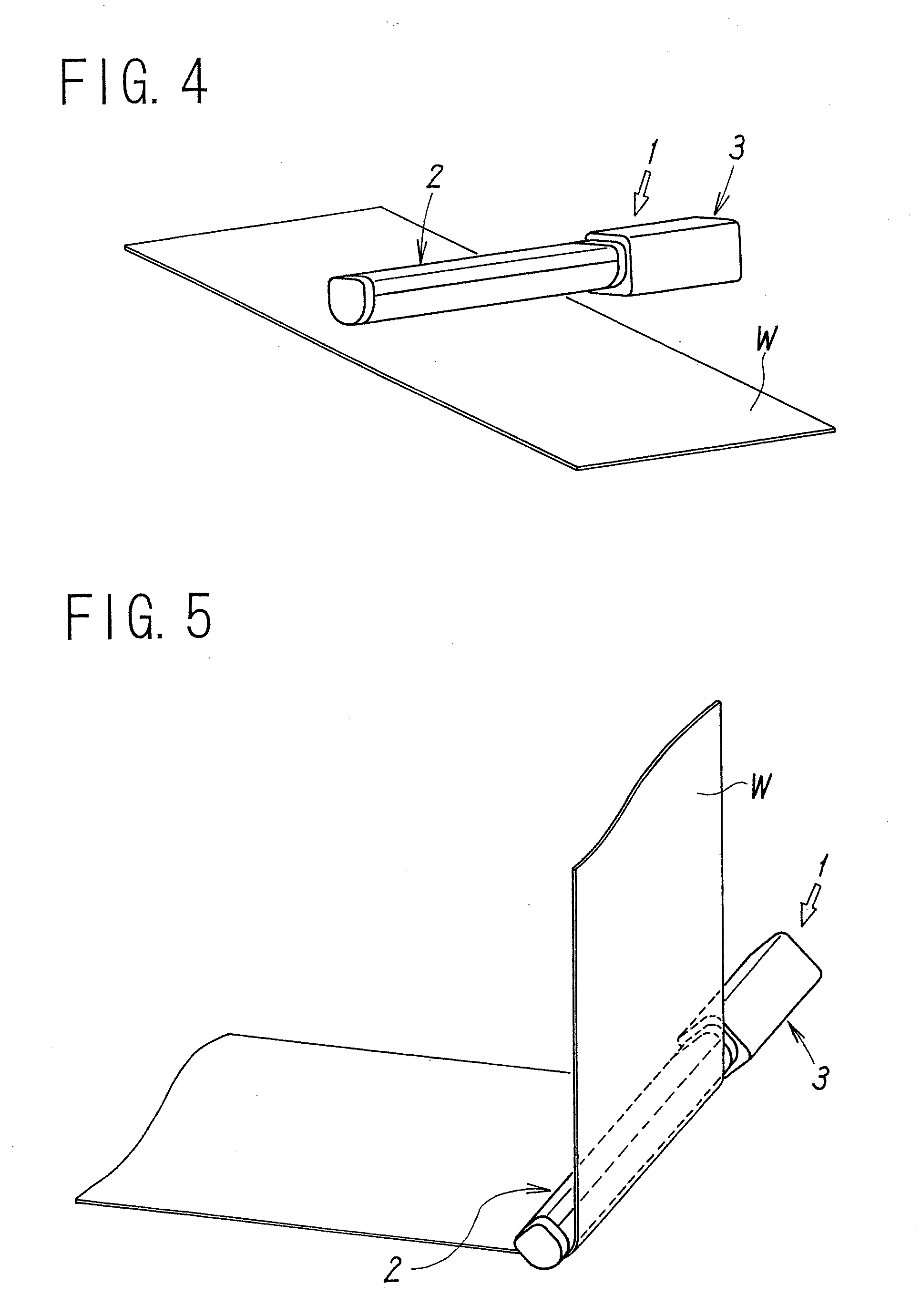
[0050]An embodiment of a static eliminator according to the present invention is shown by the drawings. The static eliminator 1 is a static eliminator of a pulse DC system and, as shown in FIGS. 1 to 4, is equipped with an ion discharge head 2 having an elongated bar shape and a storage box 3 attached at one end of the ion discharge head 2 in the longitudinal direction. Positive and negative discharge needles 5a, 5b for discharging ions by corona discharge are provided to the ion discharge head 2, and as shown in FIG. 6 and FIG. 7, positive and negative high voltage generating circuits 20a, 20b for applying a high voltage to the discharge needles 5a, 5b and a control circuit 21 for controlling the operation of the whole static eliminator 1 by controlling the positive and negative high voltage generating circuits 20a, 20b with a MPU are stored in the storage box 3.

[0051]Note that, in the description described below, the positive and negative discharge needles 5a, 5b shall be indicate...


PUM


Abstract

A static eliminator that can be placed at a close distance capable of eliminating static electricity while preventing furious elevation of the surface electric potential of a work when the static eliminator is placed at a close distance to the work. A cover formed by an electro conductive porous material covering discharge needles is attached to a holding member in which a plurality of the discharge needles are provided and air blowing openings for ejecting air around the discharge needles are provided. The cover evenly discharges ionized air from the surface of the cover, and is electrically connected to ground to have a function for absorbing a part of generated ions.

Description

TECHNICAL FIELD[0001]The present invention relates to a static eliminator for eliminating static electricity from a charged work, and in particular, to a static eliminator capable of eliminating static electricity under the state where the static eliminator is placed at a close distance to the work.BACKGROUND ART[0002]A static eliminator of a corona discharge system has been well known as a device for eliminating static electricity from a charged work. In particular, a static eliminator of a pulse DC system discharges a large amount of ions as compared with another system and is a system capable of generating ions by a plurality of discharge needles connected to a single high voltage generating circuit and has been often used for a static eliminator or the like of a bar type.[0003]However, the static eliminator using a pulse DC system generates a large amount of ions, so that when the static eliminator is placed at a close distance (for example, not more than 100 mm) to a work which...

Claims


Application Information

Patent Timeline
IPC IPC(8): H05F3/00
CPCH01T23/00H01T19/04H05F3/04
Inventor FUJIWARA, NOBUHIROKUSABA, NORIAKIYASUOKA, TAKASHISUZUKI, SATOSHI
Owner SMC CORP
Learn More