
Piezoelectric Vibrational Energy Harvesting Systems Incorporating Parametric Bending Mode Energy Harvesting

a vibrational energy harvesting and parametric bending technology, applied in the field of vibrational energy scavenging, can solve the problems of significant problems and expense, and the sensor node may be subjected to fairly predictable and/or constant vibrations

Active Publication Date: 2010-03-25
UNIVERSITY OF VERMONT
View PDF46 Cites 43 Cited by
  • Summary
  • Abstract
  • Description
  • Claims
  • Application Information

AI Technical Summary

Problems solved by technology

Of course, each of these devices requires some sort of standalone power supply to work.
However, for wireless sensor nodes designed to function beyond the typical lifetime of such batteries, at some point the batteries would have to be replaced.
This could cause significant problems and expense depending on the number of nodes at issue and the accessibility of those nodes, not to mention the need to dispose of the batteries.
However, there will be many instances when the ambient environment does not include sufficient amounts of light, air movement, temperature fluctuation and pressure variation to provide enough power to power a particular wireless sensor node.
However, the sensor node may be subjected to fairly predictable and / or constant vibrations, for example, emanating from the structure supporting the node or to which the node is attached.
This becomes problematic under any one or more of a variety of circumstances, such as when the wireless sensor node is subjected to temperature variations that change the tuning of the PVEH, when the frequency of the ambient vibrations varies over time and when the manufacturing methods used to make the PVEH cause variation in the as-built tuning of the PVEH.

Method used


Image

  • Piezoelectric Vibrational Energy Harvesting Systems Incorporating Parametric Bending Mode Energy Harvesting
  • Piezoelectric Vibrational Energy Harvesting Systems Incorporating Parametric Bending Mode Energy Harvesting
  • Piezoelectric Vibrational Energy Harvesting Systems Incorporating Parametric Bending Mode Energy Harvesting

Examples


Embodiment Construction

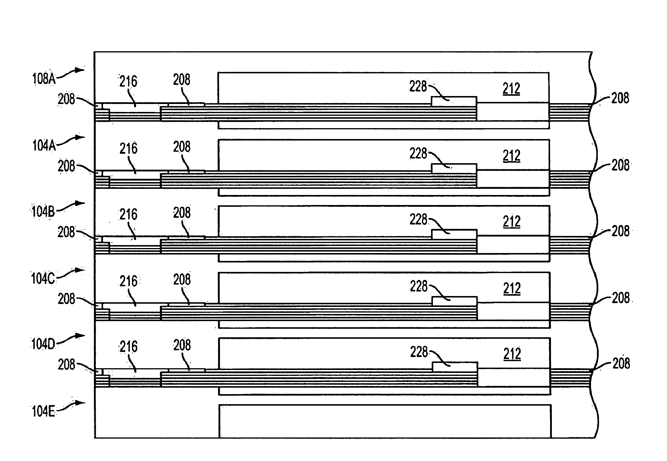
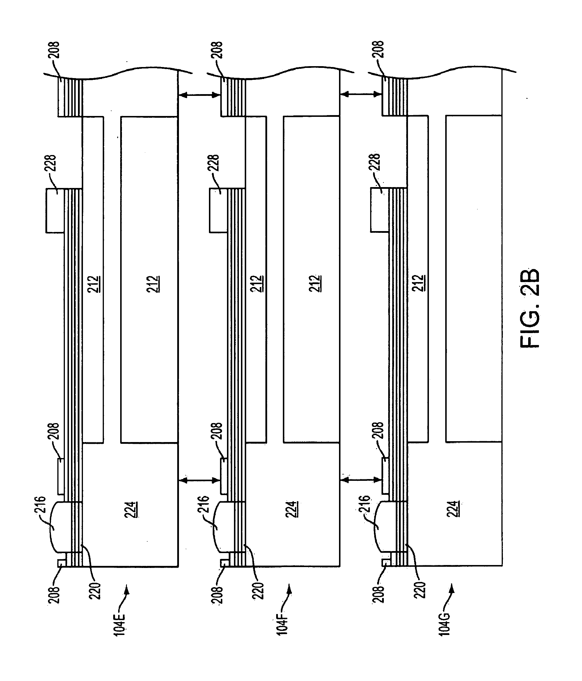
[0026]Referring now to the drawings, FIG. 1 illustrates an example of a piezoelectric vibrational energy harvester (PVEH) unit 100 made in accordance with concepts of the present disclosure. As those skilled in the art will appreciate, such a PVEH unit may be used to generate electrical power from scavenged vibrational energy in the ambient environment in which the PVEH unit is mounted or otherwise placed. Although the illustrated PVEH unit 100 of FIG. 1 is in the microscale size regime—this particular example is roughly a rectangular parallelepiped of about 7.5 mm along each base edge and 13.5 mm along the height—other PVEH units made in accordance with concepts of the present disclosure can be alternatively constructed in another size regime, such as a mesoscale-size regime, using fabrication techniques that will be readily understood by those skilled in the art. Because of the size of exemplary PVEH unit 100, those skilled in the art will recognize that it can be made using MEMS ...


PUM


Abstract

Vibrational energy harvesting (VEH) structures that include resonant beams each having a fundamental resonance frequency and a parametric mode frequency and including at least one piezoelectric layer for generating electrical charge in response to each of fundamental-resonance excitation and parametric-mode excitation of that beam. Circuitry is provided for harvesting the electrical charge from the resonant beam. In some embodiments, the parametric mode frequency of the beam is tuned to be close to its fundamental resonance frequency so as to increase the effective bandwidth of a VEH structure. The effective bandwidth of a VEH structure can be further increased by tuning ones of multiple parametric-mode-enabled resonant beams to slightly different fundamental resonance frequencies and parametric mode frequencies.

Description

RELATED APPLICATION DATA[0001]This application claims the benefit of priority of U.S. Provisional Patent Application Ser. No. 60 / 896,077, filed on Mar. 21, 2007, and titled “MEMS-Based Vibrational Power Scavenger,” which is incorporated by reference herein in its entirety.FIELD OF THE INVENTION[0002]The present invention generally relates to the field of vibrational energy scavenging. In particular, the present invention is directed to piezoelectric vibrational energy harvesting systems incorporating parametric bending mode energy harvesting.BACKGROUND[0003]Over the last quarter-century there has been a drastic increase in the level of integration of integrated circuits (ICs). At the same time, there has been a corresponding significant decrease in the feature size of ICs. For example, the width of a MOSFET (metal-oxide-semiconductor field-effect transistor) gate is presently on the order of 45 nm and is projected to be 18 nm in 2010. This is less than 1 / 500 the width of a human hai...

Claims


Application Information

Patent Timeline
IPC IPC(8): F03G7/08H02N2/18H01L41/047H01L41/113
CPCH02N2/188H01L41/1136H10N30/306H02N2/00H10N30/30
Inventor ANDOSCA, ROBERT G.WU, JUNRU
Owner UNIVERSITY OF VERMONT
Learn More