Heat exchanger, exhaust gas recirculation system, charge air supply system, and use of the heat exchanger

a heat exchanger and charge air technology, applied in indirect heat exchangers, machines/engines, lighting and heating apparatus, etc., can solve the problems of longer heat exchanger lifetime, and achieve the effect of reducing mechanical stresses, particularly those caused by thermal loads, and prolonging the life of the heat exchanger

Active Publication Date: 2010-03-25
MAHLE INT GMBH
View PDF11 Cites 20 Cited by
  • Summary
  • Abstract
  • Description
  • Claims
  • Application Information

AI Technical Summary

Benefits of technology

[0010]It is therefore an object of the present invention to provide a heat exchanger, as well as a device and a use, by which mechanical stresses, particularly those caused by thermal loads, are reduced. This is to be made possible particularly also for increased load and operating states of modern engines, particularly diesel engines, and thus result in a longer heat exchanger lifetime.
[0018]According to another embodiment of the invention, it is provided that the block closure element can be fixed at a second point on the housing and the fluid connection is fixed at a first point on the housing, the first point and the second point being spaced apart along a longitudinal extension of the housing, i.e., usually in the direction of flow of the first fluid. This has the advantage that the fixing points of the block closure element and of the fluid connection, therefore, for example, two welded seams, are separated from one another not only by the housing wall but, moreover, can also be separated by a longitudinal distance which again can be designed larger. Preferably, the second point is closer to the end of the housing than the first point. In other words, preferably the fluid connection is slipped over the housing.
[0022]A flow channel, for the first fluid, can be essentially formed in a different way. The concept of the invention is especially preferably suitable for a heat exchanger with a flow channel for the first fluid, which is made in the shape of the tube. The concept of the invention, however, can also be used in a heat exchanger in which a flow channel, preferably for the first fluid, is made in the shape of plates joined one on top of another. These and other flow channels can advantageously have a heat-conducting member, particularly in form of a fin, preferably in form of an inner fin attached to an inner channel surface and / or in form of an outer fin attached to an outer channel surface. A heat exchanger to improve the heat transfer between the first fluid and the second fluid can also have a flow guidance device, particularly a turbulence device, which usually facilitates improved fluid convection.
[0027]Overall, because of the structural separation from the fluid connection and block closure element by the housing, the concept of the invention results in a longer heat exchanger lifetime and generally leads to a higher load limit in comparison with heat exchanger designs according to the conventional art. Thereby, other fields of application for a heat exchanger can be opened or greater customer requirements can be met.

Problems solved by technology

This is to be made possible particularly also for increased load and operating states of modern engines, particularly diesel engines, and thus result in a longer heat exchanger lifetime.

Method used


Image

  • Heat exchanger, exhaust gas recirculation system, charge air supply system, and use of the heat exchanger
  • Heat exchanger, exhaust gas recirculation system, charge air supply system, and use of the heat exchanger
  • Heat exchanger, exhaust gas recirculation system, charge air supply system, and use of the heat exchanger

Examples


Embodiment Construction

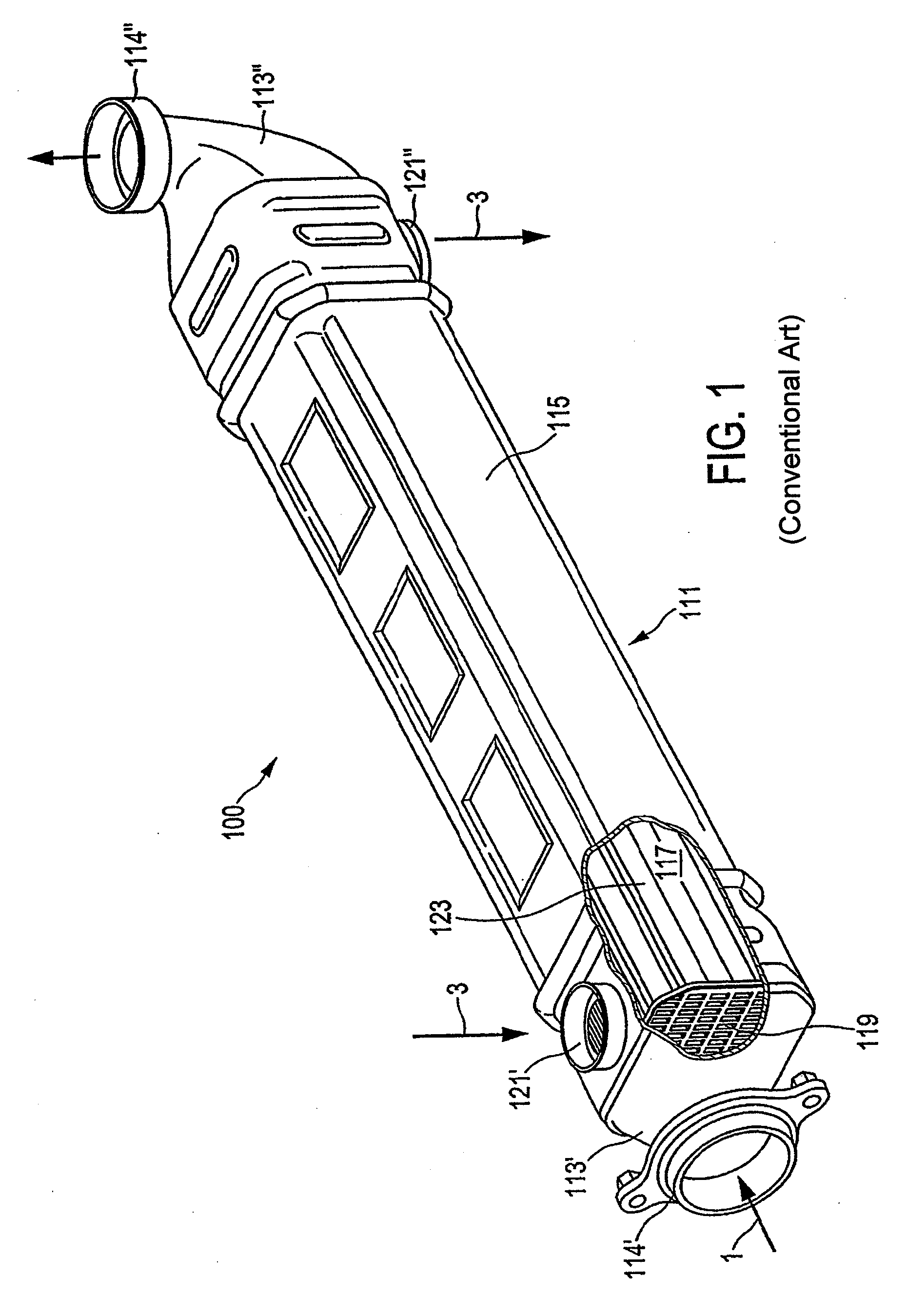
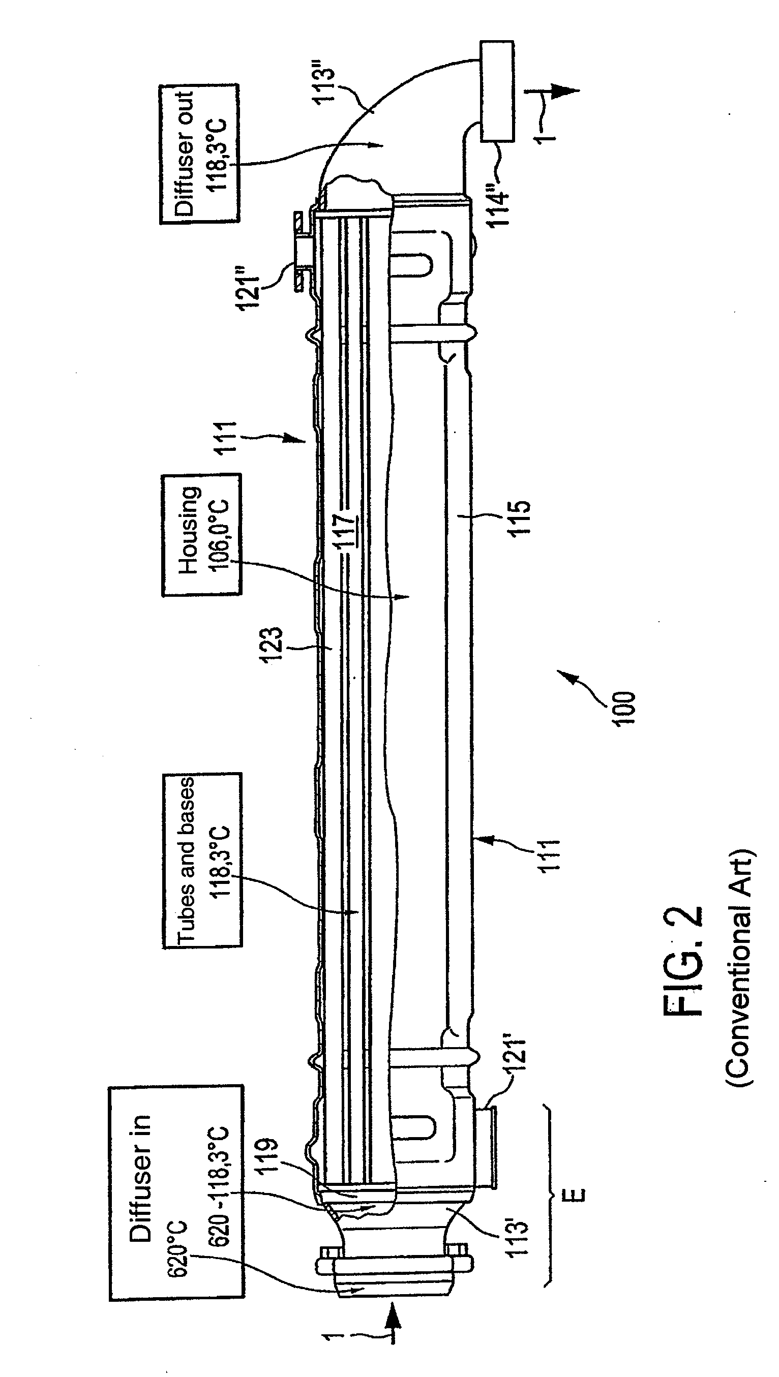
[0035]FIG. 1 and FIG. 2 show, for an overview, a heat exchanger 100 according to the conventional art in the form of an exhaust gas heat exchanger for heat transfer between a first fluid 1 in the form of an exhaust gas and a second fluid 3 in the form of a coolant. To this end, heat exchanger 100 has a block 111 for the separate and heat-exchanging guiding of first fluid 1 and second fluid 3, as well as fluid connection 113 for first fluid 1. In the present case, a fluid connection 113 is formed, on the one side, as an inlet diffuser 113′ or, on the other side, as an outlet diffuser 113″, which can be connected in each case via a flange 114′, 114″ to the periphery of an exhaust gas recirculation system, not shown in greater detail. Block 111 has a housing 115 with a chamber 117, through which second fluid 3 can flow, and a block closure element 119 for fluid-tight separation of chamber 117 and an interior space of fluid connection 113. Housing 115 to this end accommodates in chamber...


PUM

PropertyMeasurementUnit
temperatureaaaaaaaaaa
temperaturesaaaaaaaaaa

Abstract

A heat exchanger for heat exchange between a first fluid and a second fluid is provided that includes: a block for guiding the first fluid and the second fluid separately and in a heat-exchanging manner, and a fluid connection for the first fluid. The block comprises a housing provided with a chamber through which the second fluid can flow, and a block end element for the fluid-tight separation of the chamber and the fluid connection. The housing can be provided for connecting the block to the fluid connection. The block end element is not used to connect the block to the fluid connection but rather preferably only the housing. The housing can be thickened accordingly in the region of the block connection. The fixing point for the block end element to the housing and the fixing point for the fluid connection to the housing are at a distance from each other.

Description

[0001]This nonprovisional application is a continuation of International Application No. PCT / EP2008 / 01531, which was filed on Feb. 27, 2008, and which claims priority to German Patent Application No. DE 10 2007 010 134.3, which was filed in Germany on Feb. 28, 2007, and which are both herein incorporated by reference.BACKGROUND OF THE INVENTION[0002]1. Field of the Invention[0003]The present invention relates to a heat exchanger for heat transfer between a first fluid and a second fluid, comprising: a block for the separate and heat-exchanging guiding of the first and second fluid, and a fluid connection for the first fluid; the block which has a housing with a chamber, through which the second fluid flows, and a block closure element, also called a base, for separating the chamber and the fluid connection, and / or an interior space of the fluid connection. The invention relates further to an exhaust gas recirculation system, a charge air supply system, and use of the heat exchanger ...

Claims


Application Information

Patent Timeline
Patent Type & Authority Applications(United States)
IPC IPC(8): F01P11/10F28D7/00
CPCF28F9/0219F28F9/0224F28D7/1653F28D2021/0082Y02T10/121Y10T29/49393Y02T10/16F28D21/0003F02M25/0737F02M26/32Y02T10/12
Inventor GAENSLER, MICHAELGRUDEN, IGORWADER, HEIKOWELLER, WOLFGANGVON ESEBECK, GOETZDANIELSSON, DENNIENEHER, STEFANLANG, CLAUDIABLANKE, REINHARD
Owner MAHLE INT GMBH
Why Eureka
Try Eureka