Cylinder apparatus

a cylinder and cylinder body technology, applied in the direction of rotary clutches, braking systems, fluid couplings, etc., can solve the problems of deteriorating operation feeling, complicated structure of the cylinder apparatus, and ineffective strokes brought into unstable states, so as to reduce ineffective strokes and improve operation. , the effect of simple structur

Active Publication Date: 2010-03-25
HITACHI ASTEMO LTD
View PDF3 Cites 0 Cited by
  • Summary
  • Abstract
  • Description
  • Claims
  • Application Information

AI Technical Summary

Benefits of technology

[0009]Consequently, an object of the present invention is to provide a cylinder apparatus capable of reducing the ineffective stroke with a simple structure and providing excellent operation feeling.
[0041]According to the cylinder apparatus of the present invention, by providing the abutting force maximum portion on the base portion side in the inner circumferential surface of the cup seal, it is possible to reliably set the point where the piston is actuated to start the pressurization of the hydraulic fluid. In particular, since, by providing the abutting force maximum portion on the inner circumferential surface of the base portion, the pressurization of the hydraulic fluid is started at the point when the communication port provided in the piston passes the inner circumferential surface of the base portion, it is possible to reduce the ineffective stroke. In addition, it is possible to suppress an increase in the sliding resistance of the entire cup seal to the piston to the minimum and obtain excellent operation feeling when compared with case where the abutting force of the entire inner circumferential surface is increased.
[0042]In particular, by providing the abutting force maximum portion within the range of the cylindrical surface in parallel with at least one of the inner circumferential surface of the cylinder bore and the outer circumferential surface of the piston, it is possible to achieve the stabilization of the abutting force by the cooperation with the base portion disposed in a radial direction, and make the shape of the inner circumferential lip portion simple when compared with the case where a large concave and a large convex are provided on the inner circumferential surface.
[0043]Further, by forming the inner circumferential surface at a position closer to the cylinder bore bottom portion than the abutting force maximum portion into the conical surface of which diameter gradually reduces toward the cylinder bore bottom portion, it is possible to stably secure a sealing property during the rise in the hydraulic pressure by elasticity of the tip end side of the inner circumferential lip portion.
[0044]Furthermore, the contact pressure adjustment portion is preferably the conical surface in which distance between the base end surface and an opening-side-surface of the seal groove becomes gradually large toward the inner circumference from the abutment surface, and contact pressure adjustment portion intersects with a cylindrical plane of the cylinder bore at an acute angle. According to this structure, it is possible to press the abutting force maximum portion against the piston during the rise in the hydraulic pressure with enhanced reliability.
[0045]Consequently, since an improvement in the sealing property and stabilization of the ineffective stroke may be achieved, by applying the cylinder apparatus of the present invention to, e.g., a hydraulic pressure master cylinder for a vehicle of a brake system having a brake control mechanism, it is possible to obtain excellent operation feeling and stably obtain reliable brake control.

Problems solved by technology

Thus, the problem is encountered that the structure of the cylinder apparatus becomes complicated.
In addition, as described in the JP-A-2005-186925, in the cup seal in which the entire inner circumferential surface of the inner circumferential lip portion is caused to abut against the piston, a seal position for determining a point where pressurization starts at the time of start of the operation of the piston becomes unclear so that there are cases where the ineffective stroke is brought into an unstable state.
However, a sliding resistance to the piston is increased so that the problem is encountered that operation feeling is deteriorated.

Method used


Image

  • Cylinder apparatus
  • Cylinder apparatus
  • Cylinder apparatus

Examples


Embodiment Construction

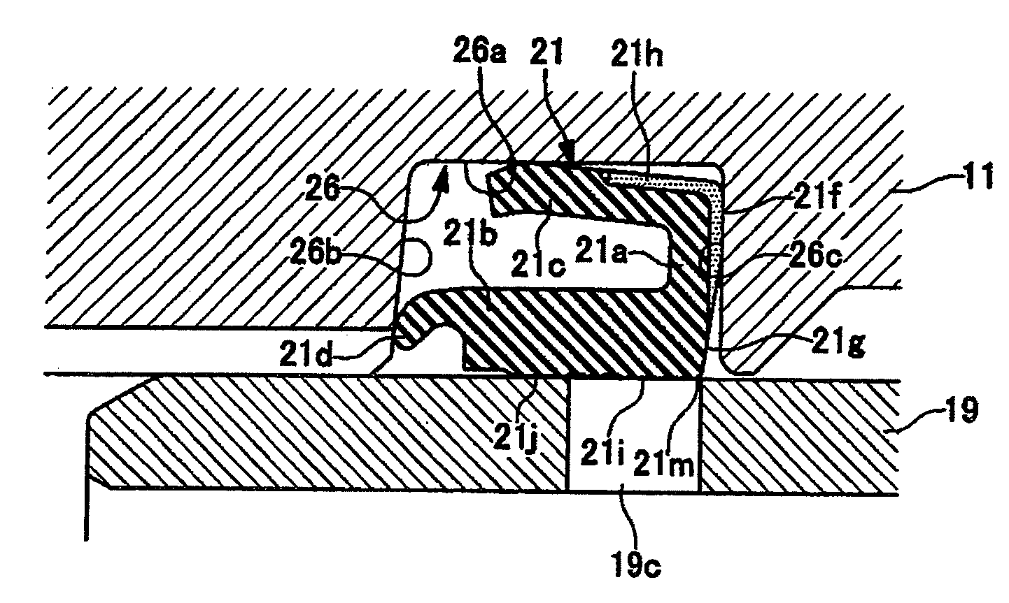
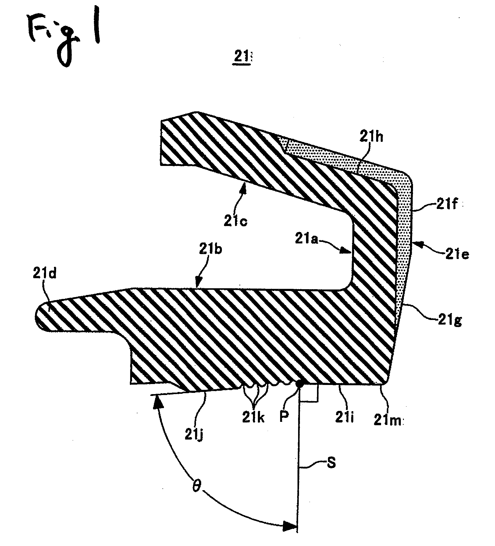
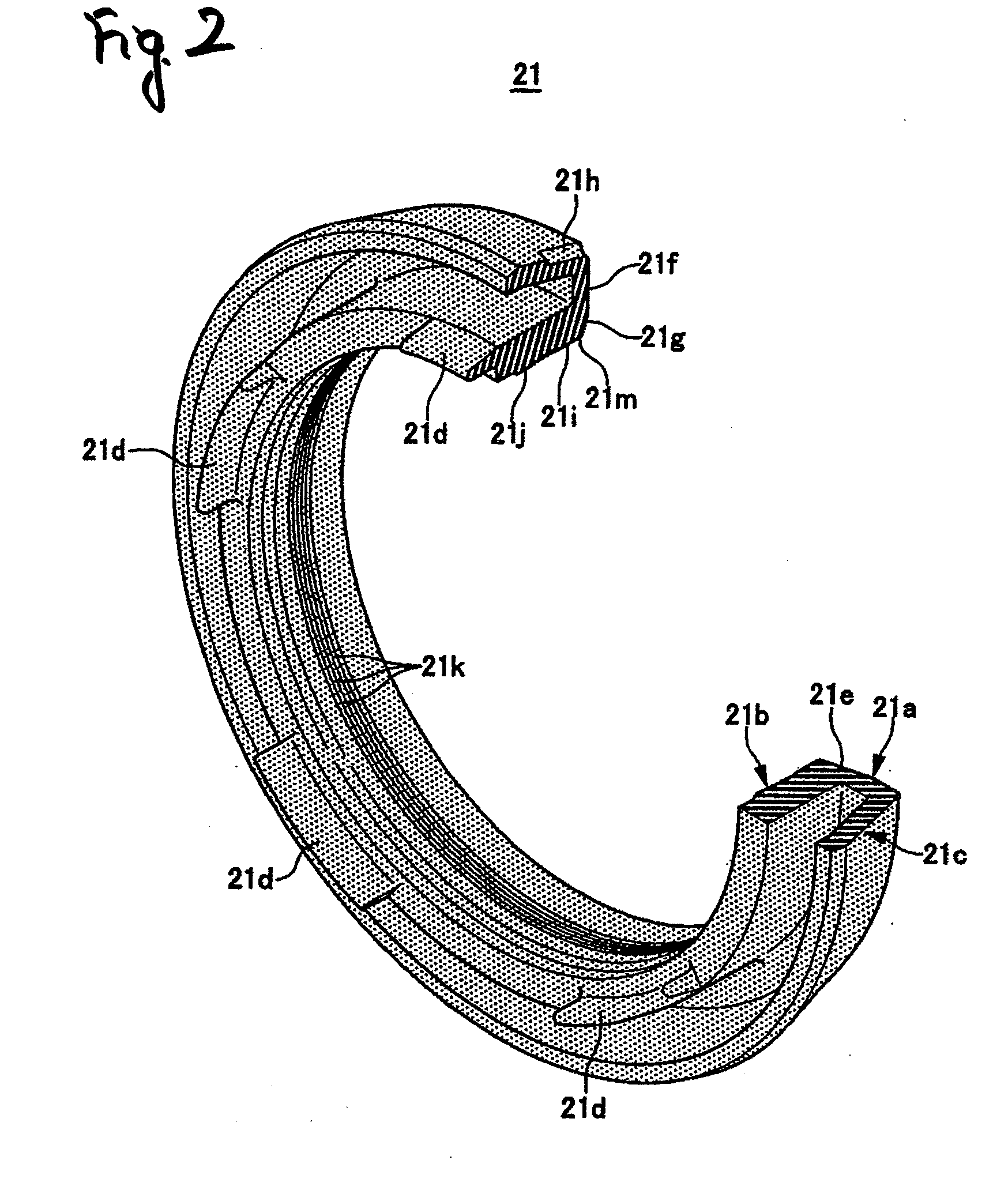
[0051]FIGS. 1 to 5C show one embodiment in which the cylinder apparatus of the present invention is applied to a hydraulic pressure master cylinder for a vehicle of a plunger type.

[0052]First, as shown in FIG. 3, in a hydraulic pressure master cylinder 10, a bottomed cylinder bore 12 is formed in a cylinder body 11. The cylinder body 11 is formed with a first output port 13 opened in the middle portion in an axial direction of the cylinder of the cylinder bore 12 and a second output port 14 opened on the bottom portion side of the cylinder bore 12. In addition, a pair of boss portions 11a and 11a is provided to be protruded on the upper portion of the cylinder body 11. First and second fluid passage holes 15 and 16 which communicate with the cylinder bore 12 are respectively provided in both of the boss portions 11a and 11a. A reservoir 18 is attached to the boss portions 11a and 11a via grommet seals 17 and 17.

[0053]Into the cylinder bore 12, a first plunger 19 (piston) is slidably...


PUM


Abstract

A cup seal 21 includes a base portion 21a disposed on a cylinder bore opening portion side of a seal groove, and an inner lip portion 21b extended from an inner circumferential side of the base portion toward a cylinder bore bottom portion and having an inner circumferential surface slidably abutting against an outer circumferential surface of a piston. In a state where the cup seal 21 is fitted into the seal groove and a plunger 19 is inserted into a cylinder bore 12, an abutting force maximum portion 21m where an abutting force against the plunger 19 becomes maximum within an inner circumferential surface of the cup seal 21 is provided on an end portion on the cylinder bore opening portion side of an inner circumferential surface part of the base portion 21a.

Description

BACKGROUND OF THE INVENTION[0001]1. Field of the Invention[0002]The present invention relates to a cylinder apparatus and, particularly to a cylinder apparatus in which a piston is movably inserted into a cylinder bore via a cup seal.[0003]2. Description of Related Art[0004]In a cylinder apparatus, it is known that an annular seal groove is formed on an inner circumferential surface of a cylinder bore into which a piston is movably inserted, and a cup seal for slidably sealing the portion between the cylinder bore and the piston is fitted into the seal groove.[0005]In general, as described in Japanese Patent Unexamined Publication JP-A-2004-231093, the seal groove includes: a seal groove bottom surface extending in a circumferential direction; a bottom-side-surface on a cylinder bore bottom portion side; an opening-side-surface on a cylinder bore opening portion side; and a seal groove opening opened to a piston. Further, the cup seal includes: a base portion disposed on the cylinde...

Claims


Application Information

Patent Timeline
IPC IPC(8): F16J15/16F15B15/14B60T11/16B60T11/236F16J15/3236
CPCB60T11/236
Inventor HANAOKA, MITSUHIRO
Owner HITACHI ASTEMO LTD
Why Eureka
Try Eureka