
Multivariate detection of molecules in biossay

a biosynthetic and target technology, applied in the field of multivariate detection of target molecules, can solve the problems of difficulty in separating signals from different fluorophores using interference filters, lower fluorescence detection accuracy, and number of problems and limitations, so as to achieve the effect of reducing one or more, and reducing the number of limitations

Inactive Publication Date: 2010-03-18
KONINKLIJKE PHILIPS ELECTRONICS NV
View PDF5 Cites 6 Cited by
  • Summary
  • Abstract
  • Description
  • Claims
  • Application Information

AI Technical Summary

Benefits of technology

[0011]The present invention seeks to provide an improved way of handling luminescence detection, such as in connection with performing a bio-assay, and preferably, the invention alleviates, mitigates or eliminates one or more of the above or other disadvantages singly or in any combination.

Problems solved by technology

When several different fluorophores are present in a sample under investigation, these spectra may partially overlap and it usually becomes very difficult to separate the signal from the different fluorophores using an interference filter.
With such an apparatus or other apparatuses of the prior art, a number of problems and limitations are present.
A problem relates to background signals caused by fluorophores other than the one under investigation.
Such background signals may result in a lower accuracy of the fluorescence detection.
In another problem, multiplexing is limited when several different fluorophores are present.
When the fluorescence spectra overlap, the maximum number of different fluorophores that can be used for multiplexing is limited, and the accuracy is lowered, even if multiplexing is feasible.
However due to overlap of broad spectra, this method is still somewhat inaccurate and the resulting multiplexing is limited, moreover a spectrometer is expensive and the substantial cost together with its limited added improvement, renders it unattractive in many applications.

Method used


Image

  • Multivariate detection of molecules in biossay
  • Multivariate detection of molecules in biossay

Examples


Embodiment Construction

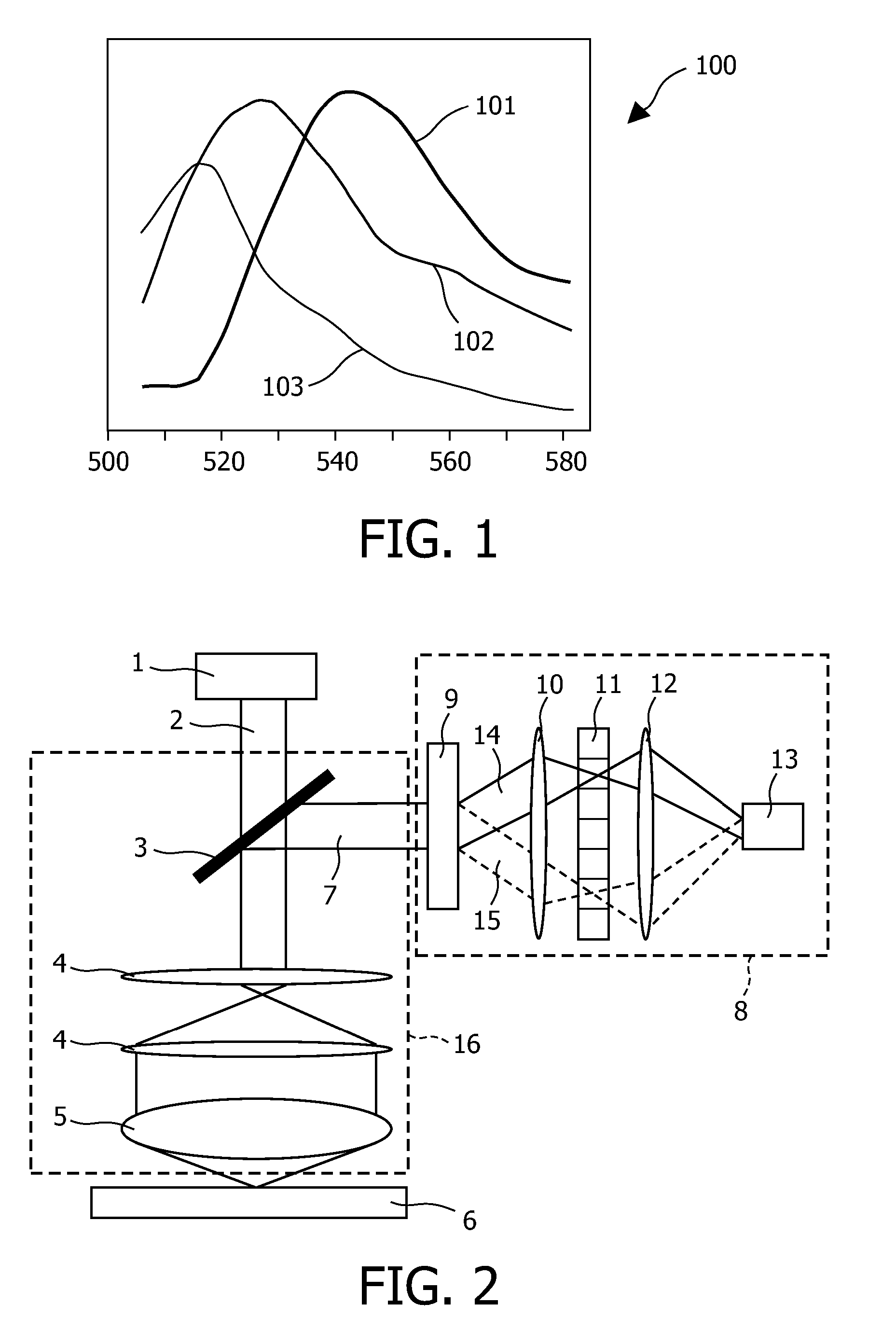
[0041]In biological research and medical diagnostics many biomarkers are detected with the aid of an attached fluorescent label. The apparatus generally used is a fluorescent scanner or microscope, generally referred to as a fluorescent biosensor, but for specific applications dedicated equipment is made based on the same detection principles.

[0042]The biomarkers are detected in connection with a bio-assay. One typical bio-assay involves immobilizing probe molecules in discrete locations on a micro-array, generally referred to as a substrate. A solution containing target molecules that bind with the attached probes is placed in contact with the bound probes under conditions sufficient to promote binding of targets in the solution to the complementary probes on the substrate to form a binding complex that is bound to the surface of the substrate. The bio-array may have a dimension in the micrometer range or even in the millimeter range. The number of different spots with distinct hyb...


PUM

PropertyMeasurementUnit
Levelaaaaaaaaaa
Luminescenceaaaaaaaaaa

Abstract

The invention relates to detection of target molecules in an assay, such as a bio-assay, and in particular to multi-variate detection of target molecules. A detector system is disclosed, the detection system comprising an optical guide element (16) for directing luminescence radiation (7) from an associated sample towards a multivariate element (8), the sample contains probe molecules that specifically binds to target molecules; a multivariate element (8) for spatially separating the luminescence radiation (7; 14; 15) to create a plurality of spectral patterns; and a detector (13) for detecting the intensity of a set of spectral patterns, so as to determine the presence of binding complexes between probe molecules and target molecules in the sample.

Description

FIELD OF THE INVENTION[0001]The invention relates to detection of target molecules in an assay, and in particular to multivariate detection of target molecules.BACKGROUND OF THE INVENTION[0002]Detection methods for particular biological molecules (bio-molecule) are manifold and many different approaches are presently available to the skilled person. The detection of specific biological molecules has a range of important practical applications, including gene identification for diagnostic purposes.[0003]In general, the detection of biological specimen (the “target”) such as polynucleotides, DNA, RNA, cells, and antibodies can especially be performed on an array for example a so-called bio-array (or micro-array) whereupon corresponding probe molecules are attached at various sites on the array. Target-probe examples include: DNA / RNA-oligonucleotide, antibody-antigen, cell-antibody / protein, hormone receptor-hormone, etc. When the target is bound or hybridised to a corresponding probe m...

Claims


Application Information

Patent Timeline
IPC IPC(8): C12Q1/68C12M1/34
CPCG01J3/02G01J3/0229G01J3/0294G01N2021/6441G01J3/36G01N21/6428G01J3/32
Inventor VAN HERPEN, MAARTEN M.J.W.VAN GOGH, ANTONIUS T.M.
Owner KONINKLIJKE PHILIPS ELECTRONICS NV
Learn More