Fuel cell system and method for controlling the fuel cell system

Active Publication Date: 2010-03-18
TOYOTA JIDOSHA KK
View PDF5 Cites 5 Cited by
  • Summary
  • Abstract
  • Description
  • Claims
  • Application Information

AI Technical Summary

Benefits of technology

[0009]The invention relates to a technology for a fuel cell system that operates with anode gas retained in each fuel or while expelling anode-off gas from a closed anode gas passage at a very low rate that prevents deterioration of the power generation performance of the fuel cell system and reduction of the durability of the electrolyte membrane of each fuel cell, which may be caused by drying of the anode of each fuel cell.

Problems solved by technology

However, because nitrogen is evenly dispersed in the anode gas in the circulation passage, if the discharge valve is operated to expel a large amount of nitrogen, a large amount of hydrogen will also be expelled together with nitrogen.
Even if the power generation efficiency of the fuel cell system is increased by reducing the nitrogen concentration in the anode gas, the waste of hydrogen immediately leads to a decrease in the fuel economy of the entire system.
As such, there is a limit to the extent to which the nitrogen concentration in the anode gas can be reduced, and thus such improvement of the power generation efficiency is limited.
However, in the dead-end type fuel cell systems and the continuous low-rate discharge type fuel cell systems, the nitrogen that has entered the anode through the electrolyte membrane is not dispersed uniformly, instead; the nitrogen accumulates in the downstream side of the anode.
For this reason, if the electrolyte membrane is insufficiently hydrated due to a shortage of moisture in the fuel cell, the conductivity decreases, which significantly reduces the power generation performance of the fuel cell.
However, in the case of the dead-end type fuel cell systems and the continuous low-rate-discharge type fuel cell systems described above, the flow of anode gas in the anode-gas passage is very weak, in particular, there is substantially no gas flow at the downstream portion of the anode.
Thus, in such fuel cell systems, water may not be dispersed adequately in the anode of each fuel cell, resulting in the anode being unevenly hydrated.
If some portions of the anode of each fuel cell are insufficiently hydrated, anode reactions do not properly occur at said portions of the anode, deteriorating the power generation performance of the fuel cell and adversely affecting the durability of the electrolyte membrane of the fuel cell.

Method used


Image

  • Fuel cell system and method for controlling the fuel cell system
  • Fuel cell system and method for controlling the fuel cell system
  • Fuel cell system and method for controlling the fuel cell system

Examples


Embodiment Construction

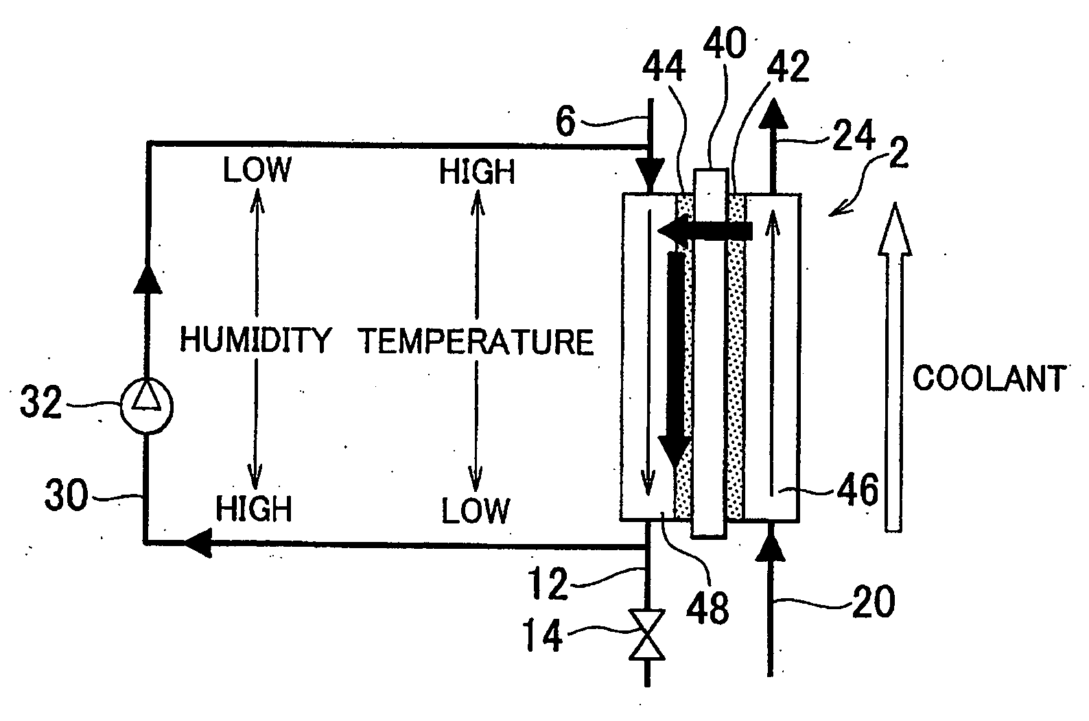
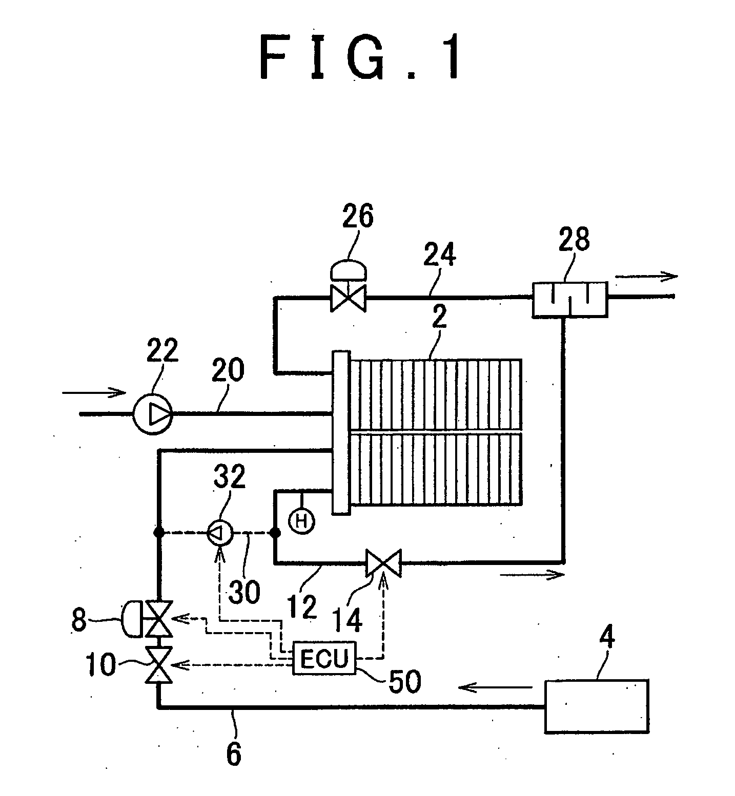
[0050]FIG. 1 is a schematic view of the configuration of a fuel cell system according to a first embodiment of the invention. The fuel cell system generates electric power using a fuel cell unit 2 and supplies the generated electric power to various electric loads, including a motor. The fuel cell unit 2 is a fuel cell stack constituted of a plurality of fuel cells stacked on top of each other. Each fuel cell is constituted of a membrane-electrode assembly and a pair of collector plates that sandwich the membrane-electrode assembly (not shown). The membrane-electrode assembly is constituted of a solid polymer electrolyte membrane, catalytic electrodes integrally provided on the both sides of the solid polymer electrolyte membrane, and gas diffusion layers formed of carbon sheets, etc., and integrally provided on the both sides of the solid polymer electrolyte membrane. Each collector plates serves also as a separator to partition the adjacent membrane-electrode assemblies. Hydrogen ...


PUM


Abstract

A gas-supply passage (6) via which anode gas is supplied to a fuel cell unit (2) and a gas-discharge passage (12) via which anode gas is discharged from the fuel cell unit (2) are connected via a communication passage (30). Circulation pump (32) switches the communication state of the communication passage between a closed state and an opened state. Circulation pump (32) causes a gas flow from the gas-discharge passage to the gas-supply passage when the communication passage (30) is in the opened state. The communication passage (30) is normally closed, and it is opened when a predetermined condition related to the operation state of the fuel cell unit (2) is satisfied.

Description

FIELD OF THE INVENTION[0001]The invention relates to a fuel cell system, and more particularly to a fuel cell system that operates with anode gas retained in each fuel cell or while continuously expelling anode-off gas from a closed anode-gas passage at a very low rate. The invention also relates to a method for controlling such fuel cell systems.BACKGROUND OF THE INVENTION[0002]For example, Published Japanese Translation of PCT Application No. 08-500931 (JP-T-08-500931), Japanese Patent Application Publications No. 2005-32652 (2-A-2005-32652), No. 2005-19331 (JP-A-2005-19331), and No. 2005-166498 (JP-A-2005-166498) describe fuel cell systems (circulation-type fuel cell systems) in which anode-off gas, which is anode gas that has been used in the fuel cells, is recirculated to utilize any unreacted hydrogen that remains in the anode-off gas. In such circulation type fuel cell systems, nitrogen that enters the anode through the electrolyte membrane of each fuel cell is also circulate...

Claims


Application Information

Patent Timeline
IPC IPC(8): H01M8/00H01M8/04
CPCH01M8/04097H01M8/0432H01M8/04514Y02E60/50H01M8/04723H01M8/04753H01M8/04559
Inventor SUEMATSU, KEIGO
Owner TOYOTA JIDOSHA KK
Why Eureka
Try Eureka