Cooling structure for turbine airfoil

Active Publication Date: 2020-01-16
KAWASAKI HEAVY IND LTD
View PDF0 Cites 1 Cited by
  • Summary
  • Abstract
  • Description
  • Claims
  • Application Information

AI Technical Summary

Benefits of technology

The present invention relates to a cooling structure for a turbine airfoil that improves cooling efficiency while reducing weight increase and durability reduction. The invention solves the problem of clogging of passages between partition plates in the lattice structure body that can lead to uneven cooling distribution and reduced durability of the airfoil. By inclining ribs in opposite directions relative to an imaginary boundary line, the cooling effect of a partition plate can be achieved without adding weight or reducing durability. The cooling medium moves from the base of the airfoil towards the tip, where the need for cooling is highest, achieving higher cooling efficiency. The cooling medium leading portion is provided to the tip portion of the airfoil for smooth discharge without compromising cooling efficiency.

Problems solved by technology

However, if a large number of partition plates are provided to the lattice structure body in order to enhance cooling efficiency, the weight of the turbine airfoil increases.
As a result, a cooling distribution in the airfoil is biased, thereby reducing the durability of the turbine airfoil.

Method used


Image

  • Cooling structure for turbine airfoil
  • Cooling structure for turbine airfoil
  • Cooling structure for turbine airfoil

Examples


Embodiment Construction

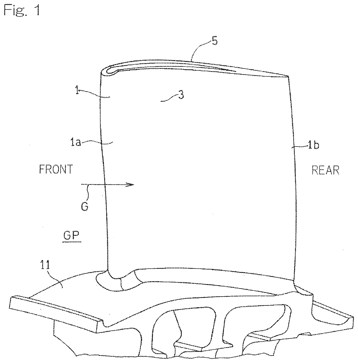
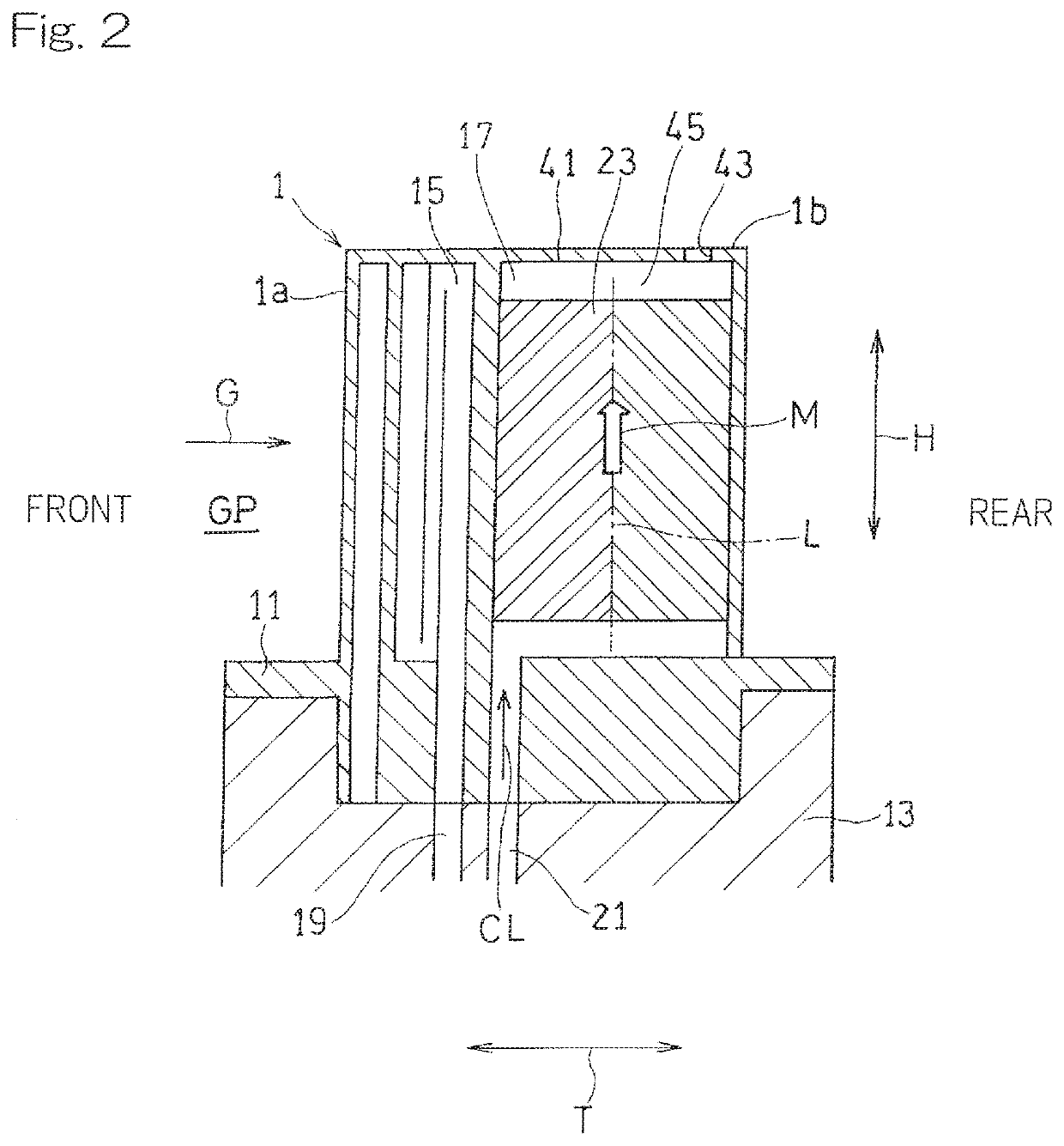
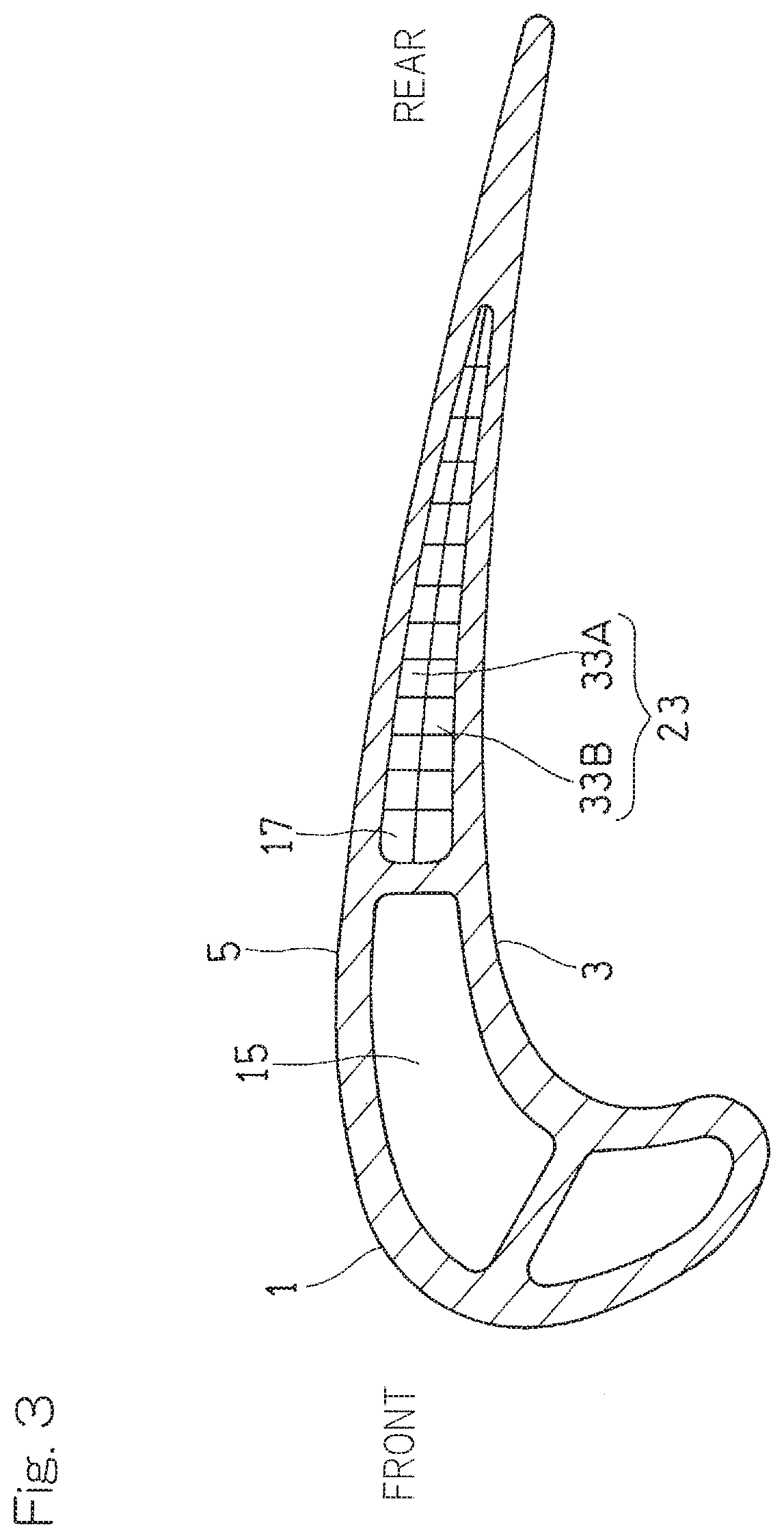
[0030]Hereinafter, embodiments of the present invention will be described with reference to the drawings. FIG. 1 is a perspective view showing a rotor blade 1 of a turbine of a gas turbine engine to which a cooling structure for a turbine airfoil according to an embodiment of the present invention is applied. The turbine rotor blade 1 forms a part of a turbine that is driven by high-temperature gas G, flowing in an arrow direction, which is supplied from a combustor that is not shown. The turbine rotor blade 1 has: a first airfoil wall 3 that is curved so as to be concave relative to a passage GP for the high-temperature gas G; and a second airfoil wall 5 that is curved so as to be convex relative to the passage GP for the high-temperature gas. In the present specification, the upstream side along the flow direction of the high-temperature gas G (the left side in FIG. 1) is referred to as a front side, and the downstream side (the right side in FIG. 1) is referred to as a rear side....


PUM


Abstract

A cooling structure for a turbine airfoil includes: a lattice structure body formed such that a first rib set and a second rib set arranged in a cooling passage are stacked on each other in a lattice pattern; and lattice communication portions that allow passages formed between ribs of the first rib set to communicate with passages formed between ribs of the second rib set. Each of the first and second rib sets has rib walls each including a pair of ribs that are inclined in directions opposite to each other relative to an imaginary boundary line extending in a movement direction of a cooling medium and that are in contact with each other on the imaginary boundary line. A plurality of lattice communication portions are formed between two lattice communication portions at opposite end portions of each rib that forms the rib wall.

Description

CROSS REFERENCE TO THE RELATED APPLICATION[0001]This application is a continuation application, under 35 U.S.C. § 111(a), of international application No. PCT / JP2018 / 008643, filed Mar. 6, 2018, which claims priority to Japanese patent application No. 2017-045925, filed Mar. 10, 2017, the disclosure of which are incorporated by reference in their entirety into this application.BACKGROUND OF THE INVENTIONField of the Invention[0002]The present invention relates to a structure for internally cooling a turbine airfoil of a gas turbine engine, that is, a stator vane and a rotor blade in a turbine.Description of Related Art[0003]A turbine that forms a part of a gas turbine engine is disposed downstream of a combustor and high-temperature gas burnt in the combustor is supplied to the turbine. Thus, the turbine is exposed to high temperatures during operation of the gas turbine engine. Therefore, it is necessary to cool a turbine airfoil, that is, a stator vane and a rotor blade. As a struc...

Claims


Application Information

Patent Timeline
IPC IPC(8): F02C7/18F01D5/18
CPCF01D5/18F02C7/18F05D2260/22141F01D5/187F05D2260/2212F05D2240/304F05D2250/185F05D2250/282F01D9/02F01D5/188F01D9/065
Inventor TSURU, TOMOKOISHIDA, KATSUHIKO
Owner KAWASAKI HEAVY IND LTD
Why Eureka
Try Eureka