
Robust Determination of the Anisotropic Polarizability of Nanoparticles Using Coherent Confocal Microscopy

a confocal microscopy and coherent technology, applied in the direction of instruments, chemical methods analysis, optical elements, etc., can solve the problem of not being detected

Active Publication Date: 2010-03-18
THE BOARD OF TRUSTEES OF THE UNIV OF ILLINOIS
View PDF13 Cites 12 Cited by
  • Summary
  • Abstract
  • Description
  • Claims
  • Application Information

AI Technical Summary

Benefits of technology

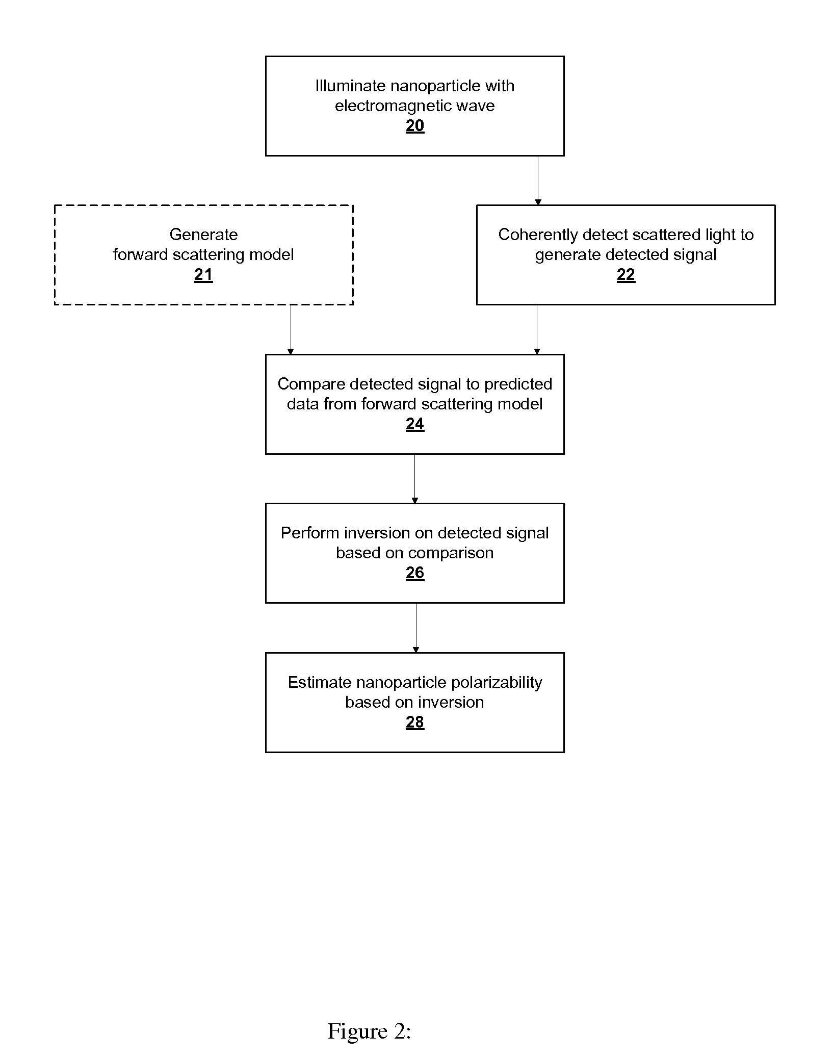
[0016]In accordance with alternate embodiments of the present invention, there may be a further step that entails varying a physical parameter of an environment in which the nanoparticle is disposed. Moreover, the step of estimating nanoparticle polarizability may include minimizing a cost function based on a norm relating the detected signal to an estimate.

Problems solved by technology

This means that potentially useful signals from a nanoparticle, such as Raman-scattered, higher-harmonic and / or fluorescent light, are not detected.

Method used


Image

  • Robust Determination of the Anisotropic Polarizability of Nanoparticles Using Coherent Confocal Microscopy
  • Robust Determination of the Anisotropic Polarizability of Nanoparticles Using Coherent Confocal Microscopy
  • Robust Determination of the Anisotropic Polarizability of Nanoparticles Using Coherent Confocal Microscopy

Examples


Embodiment Construction

[0035]Definition. As used in this description and the accompanying claims, the following term shall have the meaning indicated, unless the context otherwise requires:

[0036]An “analyzer” is any optical element that breaks the symmetry of an optical system with respect to the vector orientation of an optical field in a plane transverse to its propagation direction. Examples include both static and dynamic polarizers, whether homogeneous or patterned.

[0037]In accordance with embodiments of the present invention, a nanoparticle is parameterized by a linear polarizability tensor and a three-dimensional position. This parameterization represents prior knowledge of the object, which is used in conjunction with the instrument sensitivity to the polarization and angular distribution of the scattered light. The nanoparticle parameterization implicitly assumes that the particle is sufficiently small, in relation to the wavelength of light, to be characterized by a point polarizability. However...


PUM

PropertyMeasurementUnit
polarizabilityaaaaaaaaaa
illuminating electromagneticaaaaaaaaaa
physical parameteraaaaaaaaaa

Abstract

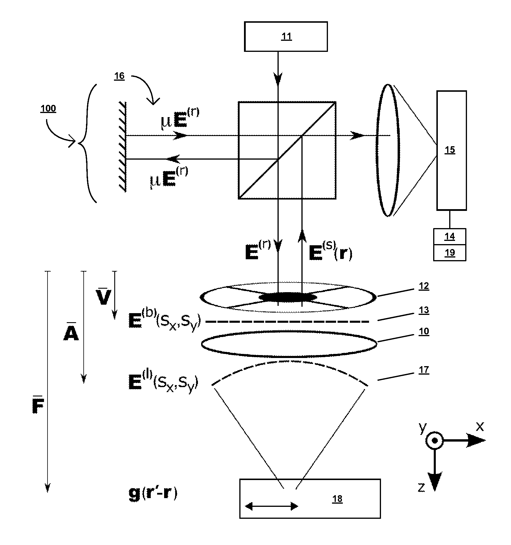
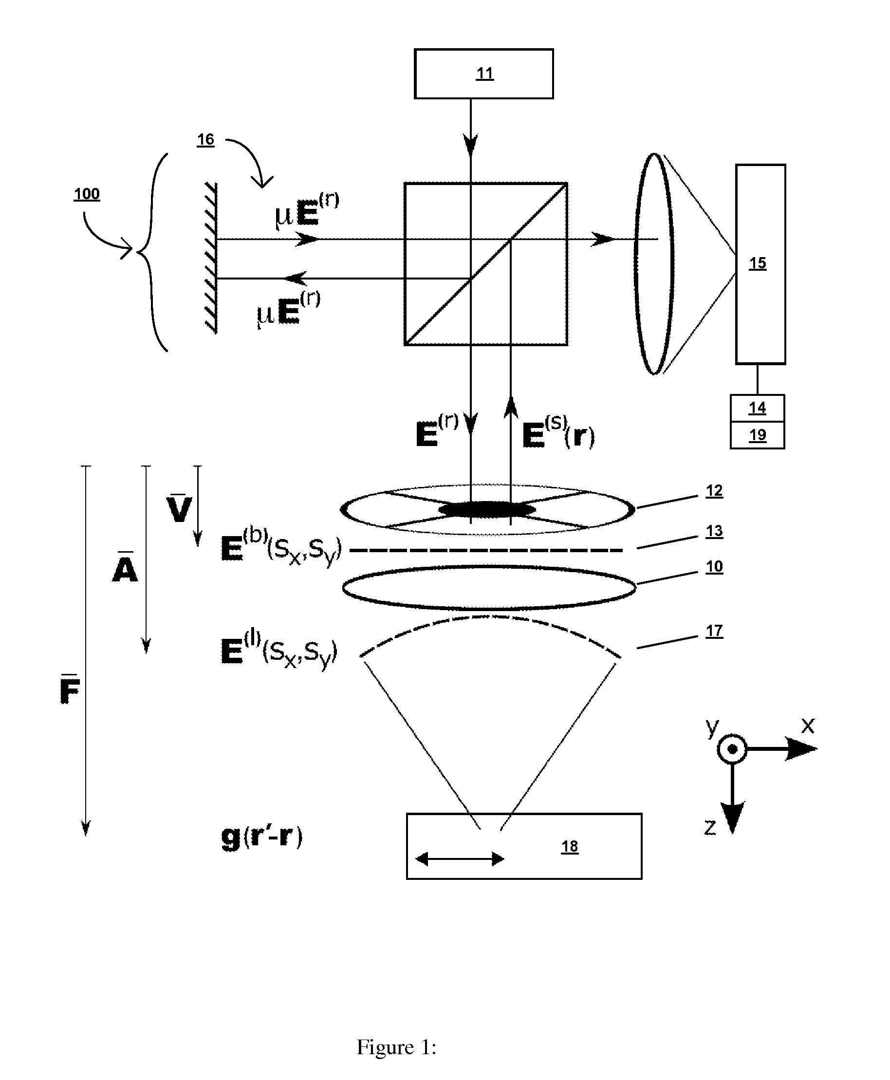
A coherent confocal microscope for fully characterizing the elastic scattering properties of a nanoparticle as a function of wavelength. Using a high numerical aperture lens, two-dimensional scanning and a simple vector beam shaper, the rank-2 polarizability tensor is estimated from a single confocal image. A computationally efficient data processing method is described and numerical simulations show that this algorithm is robust to noise and uncertainty in the focal plane position. The measurement of the polarizability removes the need for a priori assumptions regarding the nanoparticle shape.

Description

[0001]The present application claims priority from provisional application Ser. No. 61 / 037,419, filed Mar. 18, 2008, the full disclosure of which is hereby incorporated by reference herein.[0002]This invention was developed with Government support under MURI Grant No. F49620-03-10379, awarded by the US Air Force, and under NSF CAREER Grant No. 0239265, awarded by the National Science Foundation. The Government has certain rights in the invention.TECHNICAL FIELD OF THE INVENTION[0003]The present invention pertains to optical methods and apparatus for determining polarizability characteristics and locations of nanoparticles with high precision and accuracy.BACKGROUND OF THE INVENTION[0004]Nanoparticles are currently the subject of intense study as surveyed, for example, in G. Schmid, ed., Nanoparticles: From Theory to Application (Wiley, 2004), which is incorporated herein by reference. Applications are as diverse as drug delivery, sensing, bio-imaging and sorbent manufacture. Not lea...

Claims


Application Information

Patent Timeline
Patent Type & Authority Applications(United States)
IPC IPC(8): G01N21/00G06F19/00
CPCG01N21/21G02B21/0056G01N2021/4792G01N21/23
Inventor DAVIS, BRYNMOR J.CARNEY, PAUL SCOTT
Owner THE BOARD OF TRUSTEES OF THE UNIV OF ILLINOIS
Learn More