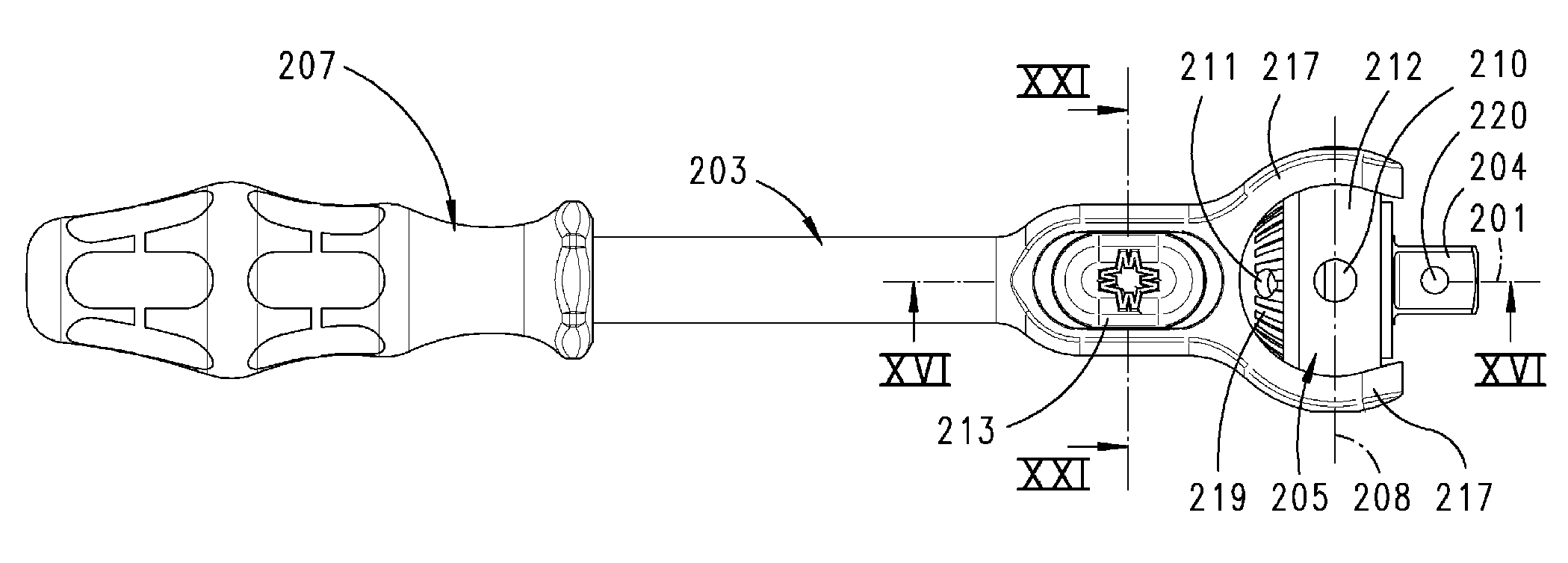
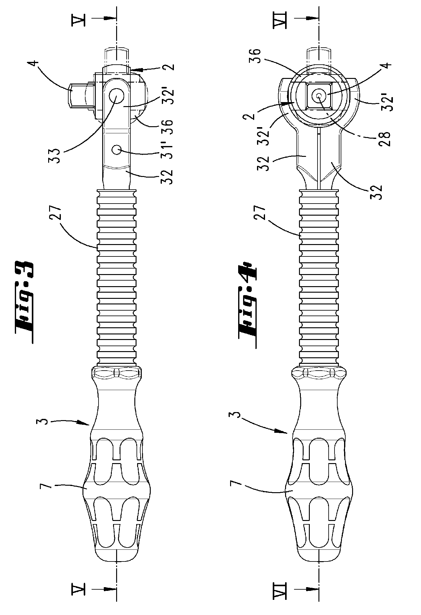
[0032]To develop the screwdriving tool known from U.S. Pat. No. 6,634,262 B2 advantageously in terms of its use, it is provided that the
detent means is a latch pin which is disposed in the drive arm and can be displaced in the direction in which the latter extends. The latch pin may in this case lie in an axial bore of the drive arm. It can be displaced from its
detent position into its release position against the
restoring force of a spring. A sliding button preferably serves for this purpose. This sliding button may be located directly adjacent the gear head, on a broad side of a widening of the drive arm. Two sliding buttons are preferably provided, located on opposite broad sides of the drive arm. These sliding buttons may be connected to each other or connected to the latch pin by means of connecting cross-pieces. The gear housing preferably has a substantially circular outer wall. On the outer wall there are two diametrically-opposed bearing openings, in which bearing pins are inserted. The pivot axis formed by the two bearing pins intersects the output rotational axis substantially at right angles. The gear housing is connected to the bearing pins by the ends of arcuate prongs of the drive arm. The two prongs form a securing fork embracing the gear housing. Midway between the two prongs, the end of the latch pin protrudes into the space defined by the fork. The latch pin can be withdrawn from the space defined by the fork by the two sliding buttons, which are coupled to one another for purposes of movement. The gear head forms a domed portion. The surface of the domed portion is part of a spherical surface. In the domed portion there are a number of detent recesses, which the end of the latch pin can enter in order to fix the gear head in various pivoted positions with respect to the drive arm. In a first pivoted position, which corresponds to a quick-action screwdriver position, the elongate axis of the drive arm lies in the output rotational axis. On the end of the drive arm there is a screwdriver handle. If this handle is turned about its elongate axis, the square drive output element of the gear head is turned about its output rotational axis. By pulling the sliding button back into a release position, the latch pin comes out of the detent recess disposed at the vertex of the domed portion. The gear head can then be pivoted about the pivot axis, for example into an intermediate position in which the output rotational axis assumes a 45° position in relation to the elongate axis of the drive arm. The gear head may, however, also be pivoted further into a 90° position, in which the drive arm lies in a power-action screwdriver position in relation to the output rotational axis. The elongate axis of the drive arm then lies in a position pivoted by 90° with respect to the output rotational axis. The detent recess in which the latch pin engages in this position is located in the annular gear housing. This detent recess lies in the same plane in which a diametrically-opposed detent recess and the two bearing pins also lie. The domed portion serves not only for the reversing of the direction of rotation of the
ratchet or
freewheel gear. The domed portion may also be displaced in the axial direction with respect to the output rotational axis. This displacement takes place against the
restoring force of a spring for the displacement of a release slide. The release slide is part of a retaining device for a socket or the like, which can be fitted onto the square drive output element. In the quick-action screwdriver position, the domed portion can be displaced with the aid of one of the two sliding buttons. For this purpose, the sliding button disposed near the root of the fork is displaced in the opposite direction, that is to say toward the securing fork, whereby the latch pin is pressed deeper into the detent recess of the domed portion. It thereby acts on the bottom of the detent recess and displaces the domed portion in the axial direction of the output rotational axis, in order to displace the release slide. The latter interacts with a detent ball, which enters a corresponding detent recess in a wall of an insert opening of the socket. The latch pin is held by two oppositely-acting compression springs in a
neutral position, from which it can be displaced either into a release position for the pivoting of the gear head or for the release of the retaining device. In the retaining position, the detent ball lies in front of a wall of the release slide. In the release position, the detent ball can move radially inward out of the way. For this purpose, the release slide has a pocket. When the release slide is displaced back into its retaining position, the ball is displaced radially outward again by a sloping side wall of the pocket. The domed portion of the gear head forms a direction
changeover switch for the
freewheel gear. A radially outer portion of the domed portion may form a fluting. This portion is accessible in every pivoted position of the gear head, so that the directional block can be reversed in each pivoted position. By way of their mutually facing inner flanks, the fork prongs that form the gear-head bearing
mount are in close surface-area contact with the convex outer surface of the gear housing. For this purpose, the inner flanks of the fork prongs are hemispherically shaped. During
assembly, the gear head can be angled into this ball mounting. The fork prongs are fixedly associated with one another. This allows maximum torques to be applied to the square drive output element.


