
Bistable Display Device

a display device and display plate technology, applied in static indicating devices, circuit electrostatic discharge protection, instruments, etc., can solve the problems of affecting the optimal operation or stability of the bistable display device, affecting the production yield of final products, and reducing the thickness of the lcds. , to achieve the effect of improving the production yield, short distance between the ports, and ensuring the final product's electrostatic protection

Active Publication Date: 2010-03-04
E INK HLDG INC
View PDF12 Cites 4 Cited by
  • Summary
  • Abstract
  • Description
  • Claims
  • Application Information

AI Technical Summary

Benefits of technology

[0007]The present invention is to provide a bistable display device wherein electrical punch-through caused by great electric potential difference and short distance between the electrical ports of the circuits is substantially avoided.
[0010]By keeping the electric potential difference between any two neighboring ports less than 10 volts, the problem of electrical punch-through caused by great electrical difference and short distance between the ports has been improved. The production yield can be improved and a certain level of electrostatic protection of the final products can be achieved. The problems in quality or reliability of the bistable display device caused by improper plugging or unplugging are alleviated so that the bistable display device including the driver IC and the FPC are protected from electrostatic punch-through.

Problems solved by technology

In other words, now it is rather difficult to further shrink the thickness of the LCDs.
During plugging and unplugging of all kinds, damages may be made to the FPC and the substrate caused by the pulling tearing, and alignment stress.
Such damage may be mechanical and / or electrical and may impair the optimal operation or the stability of the bistable display device.
If neighboring ports of the ICs in the bistable display device are separated by the same distance as in the case of a TFT LCD, when the electric potential difference between the ports is relatively large, for example, greater than or equal to 10 volts, the electrostatic interference between the ports may be quite significant, which may cause the driver IC of the bistable display device to function unstably and the image quality to be compromised.
In a worse case, the material between the neighboring ports may be electrically punched through, which may in turn cause short circuits and the whole IC to be burned and damaged.
This problem thus has become an important one in design of bistable display devices.

Method used


Image

  • Bistable Display Device
  • Bistable Display Device
  • Bistable Display Device

Examples


Embodiment Construction

[0014]Referring to FIG. 1, a driver circuit 1 of a bistable display device according to a preferred embodiment of the present invention is provided. The driver circuit 1 is intended to drive the bistable display device to display video. The driver circuit 1 has a connection portion 10 for connecting to and communicating with external circuits.

[0015]It is to be understood that the driver circuit 1 can be applied to various kinds of bistable display devices, such as electrophoretic displays and cholesteric liquid crystal displays. An example of electrophoretic displays is E-ink displays.

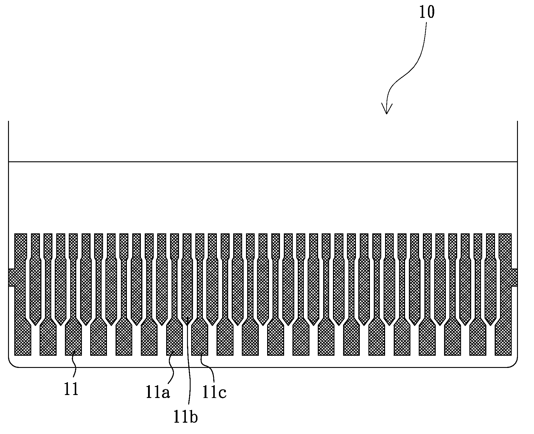
[0016]Referring to FIG. 2, a plurality of ports 11 are disposed on the connection portion 10. The connection portion 10 is electrically connected to external circuits through the ports 11. In normal operations, the voltages on the ports 11 range from 10 volts to 40 volts. In this embodiment, the electric potential difference between any two neighboring ports is less than 10 volts.

[0017]More specificall...


PUM


Abstract

In a bistable display device having a driver circuit, the driver circuit has multiple electrical ports for electrically connecting to external circuits. The electric potential difference between any two neighboring ports is less than 10 volts so that electrical punch-through caused by great electric potential difference and short distance between the electrical ports is substantially avoided.

Description

BACKGROUND[0001]1. Field of the Invention[0002]The present invention relates to a bistable display device, and more specifically, to a configuration of electrical ports of a bistable display device.[0003]2. Description of Related Art[0004]The outdoor reflective display has been widely used today. Most of such displays are used in portable devices. As a result, there has been a great demand for displays that are lightweight and small-sized and thus it is becoming more and more important to design display devices that are relatively light in weight and thin in thickness.[0005]Traditional Liquid Crystal Displays (LCDs) such as TFT (Thin Film Transistor) LCDs have been maturely developed and shrinking of the thickness of LCDs has approached to a limit. In other words, now it is rather difficult to further shrink the thickness of the LCDs. To meet the demand for products such as electronic books and electronic paper, many companies are looking at the research and development of bistable ...

Claims


Application Information

Patent Timeline
Patent Type & Authority Applications(United States)
IPC IPC(8): G06F3/038
CPCG02F1/13452G09G3/3651H05K1/0219H05K2201/09727H05K1/117H05K2201/09709H05K2201/09381H05K1/0259
Inventor SHINN, TED-HONGWU, CHI-MINGTSAI, YUAN-CHIH
Owner E INK HLDG INC
Learn More