Broadband microwave device with switchable gain

Active Publication Date: 2010-03-04
THALES SA
View PDF5 Cites 3 Cited by
  • Summary
  • Abstract
  • Description
  • Claims
  • Application Information

AI Technical Summary

Benefits of technology

[0036]Another aim is to obtain a gain adjusting mi

Problems solved by technology

Nevertheless, the use of switches C1, C2 to produce the function of FIG. 1a leads, through the high-frequency losses that they introduce, to a degradation of the noise figure NF of the receiver.
Furthermore, the use of two switches C1 and C2 to produce these gain adjusting devices leads to an increase in the losses of the microwave subsystem regardless of whether the device (or the path travelled by the signal in the subsystem) is configured to maximum gain or to minimum gain.
This solution makes it possible to increase, if necessary, the gain difference between the two states of the device but changes nothing with the drawback of increasing the noise figure due to the losses of the input switch C1.
In the state of the art of radiofrequency receivers, there is no ideal solution for avoiding a degradation of the noise figure.
However, to obtain a good noise figure NF, the reception subsystems of the state of the art usually include a low-noise amplifier (LNA) at the head of the reception subsystem, without the possibility of switching it, which has the drawback, in the case of the reception of strong signals, of introducing distortions of the received signal but also a degradation of the characteristics of the receiver, even destruction of said receiver.

Method used


Image

  • Broadband microwave device with switchable gain
  • Broadband microwave device with switchable gain
  • Broadband microwave device with switchable gain

Examples


Embodiment Construction

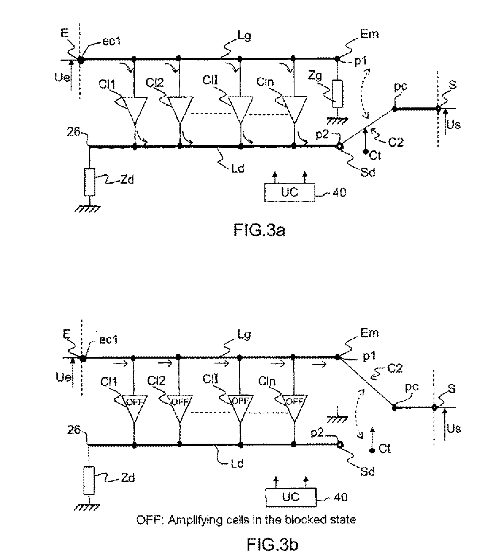
[0043]The broadband microwave device with switchable gain of FIGS. 3a and 3b comprises:

[0044]a microwave input E and output S of the device,

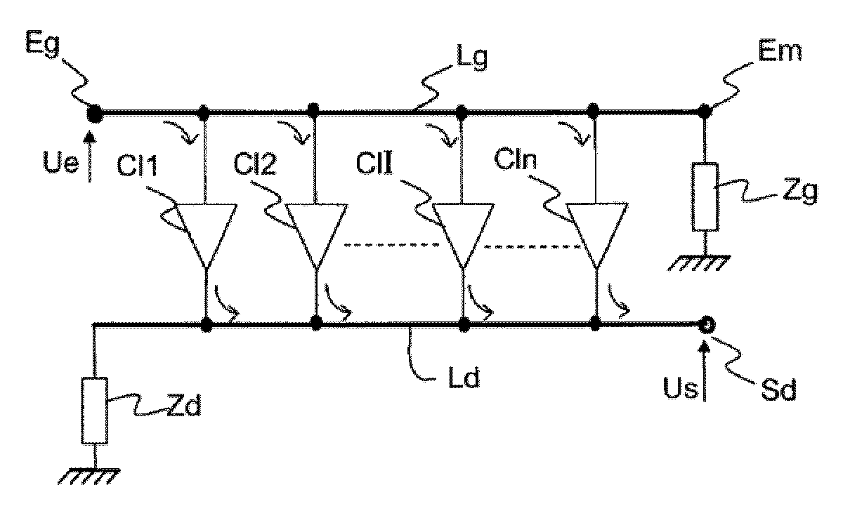
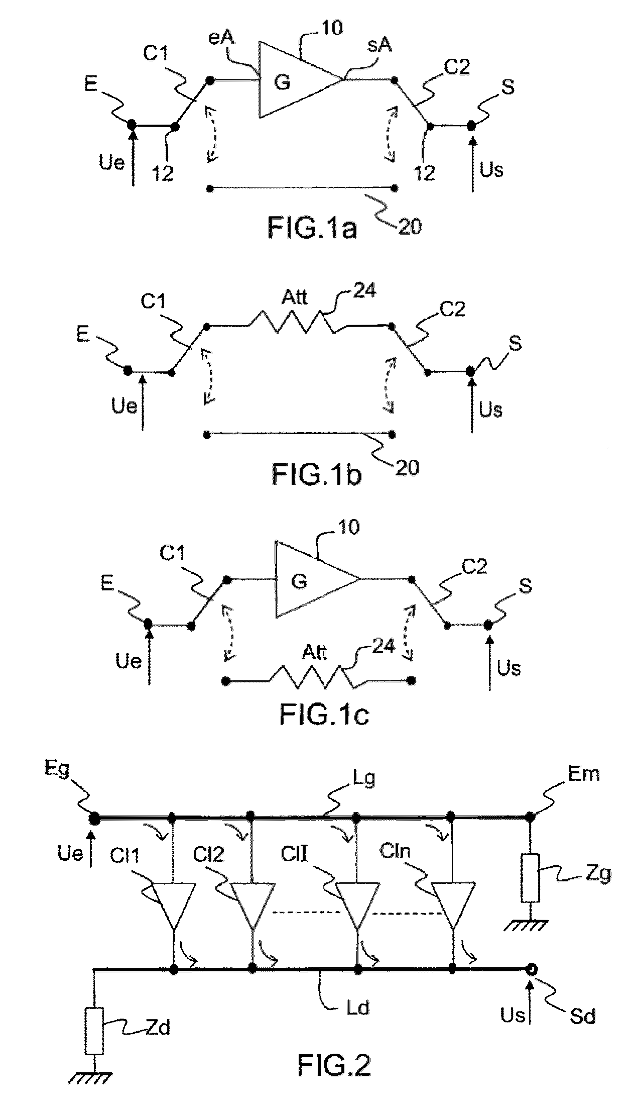
[0045]a distributed amplifier with n amplifying cells Cl1, Cl2, . . . Cli . . . Cln, comprising an input transmission line Lg for an input signal Ue applied to the microwave signal input E and an output transmission line Ld for the amplified input signal;

[0046]a switch C2 of the two-channel-to-one-channel type, having a common terminal pc and two terminals p1, p2 for choosing the channel to be switched. This switch C2 will hereinafter be designated more simply “2-to-1 switch”.

[0047]The input transmission line Lg has one of its two ends ec1 linked to the input E of the device and the other end Em linked on the one hand to the terminal p1 of the switch C2 and on the other hand to a switchable terminating impedance Zg. The term “switchable terminating impedance Zg” should be understood to mean an impedance Zg associated with a switching means in or...


PUM


Abstract

The invention relates to a broadband microwave device with switchable gain comprising a microwave signal input E and output S, a distributed amplifier with a plurality of amplifying cells comprising an input transmission line for an input signal applied to the microwave signal input E, said input transmission line having one of its two ends linked to the microwave signal input E, an output transmission line for said amplified input signal having an output end of the distributed amplifier, the cells of the distributed amplifier settable either to an amplifying state or to a blocked state. A switch switches the microwave signal output S either to a non-amplification position linked to the other end of the input transmission line, or to an amplification position linked to the output end of the distributed amplifier. A control unit supplies switch position control and amplifying cell status control signals.

Description

CROSS REFERENCE TO RELATED APPLICATIONS[0001]The present application claims priority to French Patent Application Serial No. 08 / 04764, filed on Aug. 29, 2008, the contents of which are hereby incorporated by reference in its entirety.FIELD OF THE INVENTION[0002]The invention relates to a broadband active device for microwave integrated circuits providing gain switching functions.BACKGROUND OF THE INVENTION[0003]The transmission and reception subsystems produced for example using MMIC (Monolithic Microwave Integrated Circuits) technology, generally comprise one or more gain control cells that are used to adapt, for example in the case of a radiofrequency transmission subsystem, the desired output level and, in the case of a reception subsystem, the gain of the subsystem at the received signal level.[0004]In practice, a gain control of the transmission and / or reception subsystem is sought that offers a minimum of distortion of the signal processed by the subsystem and of degradation o...

Claims


Application Information

Patent Timeline
IPC IPC(8): H03F3/16H03F3/68
CPCH03F3/72H03F3/605
Inventor PLAZE, JEAN-PHILIPPEAURIC, CLAUDEDUEME, PHILIPPE
Owner THALES SA
Why Eureka
Try Eureka