
Intercooler

a technology of intercooler and pressure loss, which is applied in the direction of combustion engine, combustion air/fuel air treatment, charge feed system, etc., can solve the problem of pressure loss rise in the intercooler

Active Publication Date: 2010-03-04
AUDI AG
View PDF23 Cites 18 Cited by
  • Summary
  • Abstract
  • Description
  • Claims
  • Application Information

AI Technical Summary

Benefits of technology

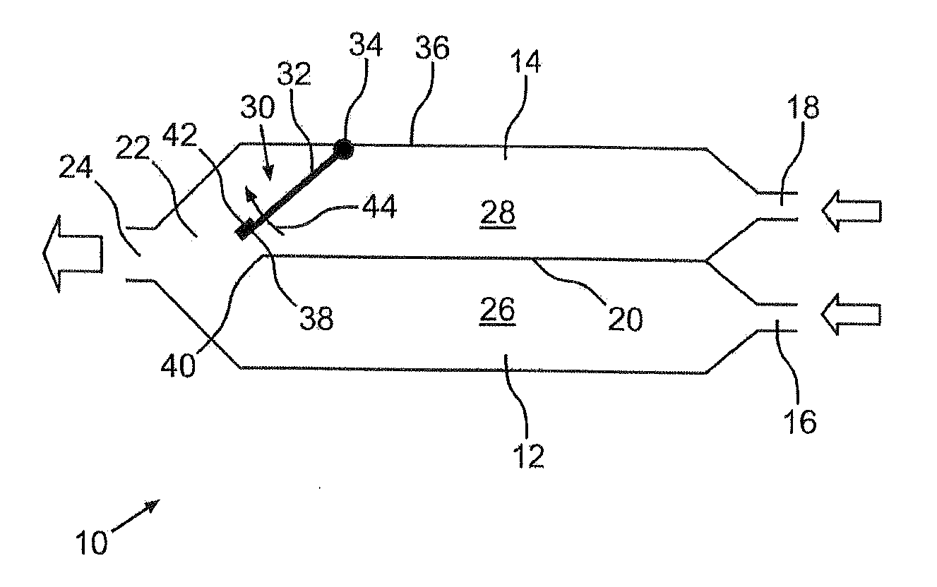
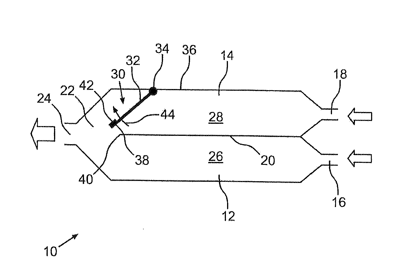
[0009]If only one supercharging assembly is in operation, the closable air channel can thus be closed. As a result, the intercooler volume is significantly reduced during operation of only one supercharging assembly. Because of the smaller volume of the intercooler that is thus available, a change in the compression by the supercharging assembly is thus advantageously relayed more quickly to the engine of the motor vehicle. In load variation processes, the response behavior of the charge is thus improved.
[0010]In addition, a higher flow rate into the intercooler is achieved by the reduced cross-section in the heat exchanger module in the operation of only one supercharging assembly. This results in improved efficiency of the heat exchanger. At the same time, as a result, the pressure losses rise in the intercooler, but the higher efficiency of the heat exchanger module over-compensates for this increase.
[0012]To facilitate the return of the closing element into its closing position, in addition a return element can be provided that exerts on the closing element a return force that is proportional to a deflection of the closing element from the closing position. This can be achieved by, for example, a correspondingly arranged spring.
[0013]So that such a closing element can completely develop the above-mentioned advantageous properties, a sealing element is preferably associated with the closing element. Thus, in particular during operation of only one supercharging assembly, pressure losses that could develop by a partial opening of the closing element are avoided.

Problems solved by technology

At the same time, as a result, the pressure losses rise in the intercooler, but the higher efficiency of the heat exchanger module over-compensates for this increase.

Method used


Image

  • Intercooler
  • Intercooler

Examples


Embodiment Construction

[0017]An intercooler that is designated as a whole as 10 consists of two separate heat exchanger modules 12 and 14. Accordingly, a first air inlet opening 16 is associated with the heat exchanger module 12. In motor vehicles with a step-by-step supercharging, in which a first supercharging assembly runs continuously and a second supercharging assembly is turned on only if necessary, the first continuously-running supercharging assembly is connected to the air intake 16 of the heat exchanger module 12. The compressor exhaust of the supercharging assembly that is turned on only if necessary is connected to a second air inlet opening, 18, which is associated with the heat exchanger module 14.

[0018]A partition 20, which separates the air streams in the heat exchanger modules 12 and 14 from one another, is arranged between the heat exchanger modules 12 and 14. These air streams are brought together again only in an air box 22 of the intercooler 10 and exit via an air outlet opening 24 fr...


PUM


Abstract

The invention relates to an intercooler for a motor vehicle with an internal combustion engine that is supercharged in steps. In this case, the intercooler has an air outlet opening as well as two air inlet openings, a heat exchanger module being associated with each air inlet opening. Air channels of the two heat exchanger modules are ultimately brought together in an air box of the intercooler, which is connected to the air outlet opening. It is thus made possible to bring together compressed charging air from two supercharging assemblies only in the area of the intercooler. To improve the pressure ratios during operation of only one supercharging assembly, a non-return valve is provided in an air channel. Thus, a module for separately bringing the airways together can be eliminated, thereby reducing the installation space requirement.

Description

[0001]the invention relates to an intercooler for a motor vehicle as well as a motor vehicle with such an intercooler.BACKGROUND OF THE INVENTION [0002]The known intercoolers for motor vehicles are used to cool the combustion air that is compressed by a supercharging assembly—such as, for example, a compressor or turbocharger—in order to further increase its air density. A larger air mass can thus be fed to the engine, as a result of which a greater amount of fuel can be injected, which increases the output of the engine.[0003]Intercoolers usually have a heat exchanger module through which charging air flows. At a network structure of the heat exchanger module, this charging air releases its heat into the ambient air. In many cases, liquid-cooled heat exchanger modules are also used for intercoolers.[0004]If exhaust-gas turbochargers are used as supercharging assemblies, their compression efficiency depends greatly on the respective operating state of the motor vehicle. To improve t...

Claims


Application Information

Patent Timeline
IPC IPC(8): F02M31/20
CPCF02B29/0412Y02T10/146F02B29/0437F02B29/0425Y02T10/12
Inventor HUBER, FRANKSONNER, MARKUS
Owner AUDI AG
Learn More