
Optical Fiber

a technology of optical fiber and protective layer, applied in the field of optical fiber, can solve the problems of increasing the transmission loss by a micro bending, the constraint of production also became large, and the inability to help becoming so complicated, so as to improve the micro bending resistance characteristic, improve the adhesion of the primary protective layer to the glass optical fiber, and increase the transmission loss

Inactive Publication Date: 2010-02-25
FURUKAWA ELECTRIC CO LTD
View PDF5 Cites 13 Cited by
  • Summary
  • Abstract
  • Description
  • Claims
  • Application Information

AI Technical Summary

Benefits of technology

The present invention aims to provide an optical fiber that has a simple coating structure and is easy to produce. The optical fiber has a primary protective layer with high adhesiveness to the glass optical fiber and low water absorption, but it also has a high glass transition temperature. This prevents delamination and bubble formation in the primary protective layer. The optical fiber has a three-layer coating structure with a high glass transition temperature for the primary protective layer and a low glass transition temperature for the secondary protective layer. This ensures high performance and reliability of the optical fiber. The thickness of the primary protective layer is made thinner than the secondary protective layer to minimize adverse effects on micro bending resistance and adhesiveness to the glass optical fiber. Overall, the optical fiber has a simple structure and is easy to produce, while also being resistant to delamination and bubble formation.

Problems solved by technology

As mentioned above, in an optical fiber, there is an issue that transmission loss increases by a micro bending when delamination arises, for example, in an interlayer between a glass optical fiber and a primary layer, or a bubble arises in a primary layer.
In addition, the structure of the optical fiber disclosed in the patent document 1 cannot help becoming such very complicated construction that a primary layer is made into two or more layers in order to solve the issue of adhesiveness, and moreover, concentration must be made high for a content of a photo-initiator as a layer becomes inside the primary layer.
Hence, constraint in view of production also became large.

Method used


Image

  • Optical Fiber
  • Optical Fiber
  • Optical Fiber

Examples


Embodiment Construction

[0040]An optical fiber of the present invention will be described below in detail using drawings.

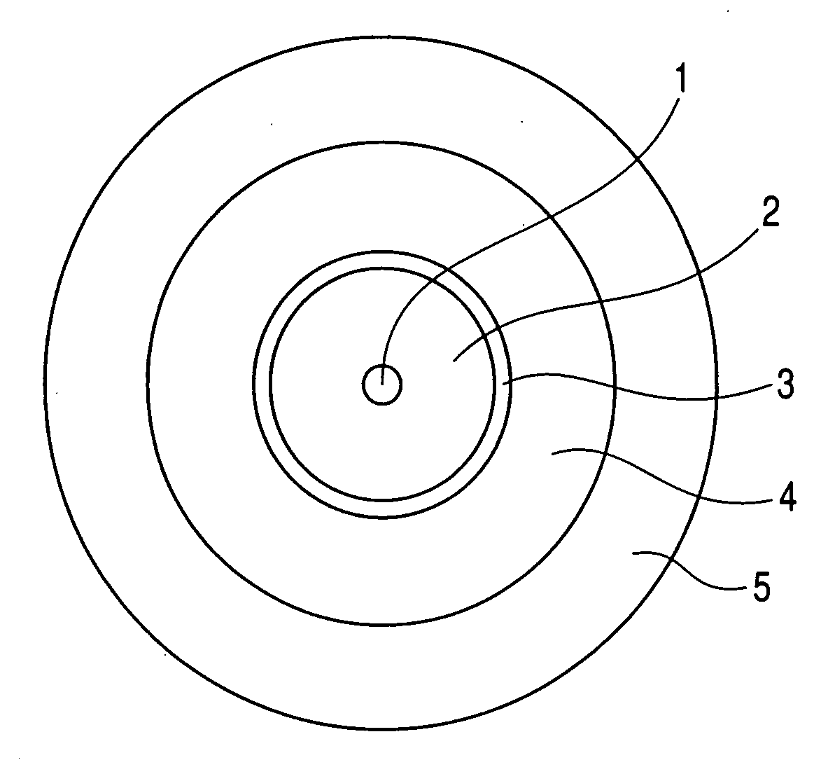
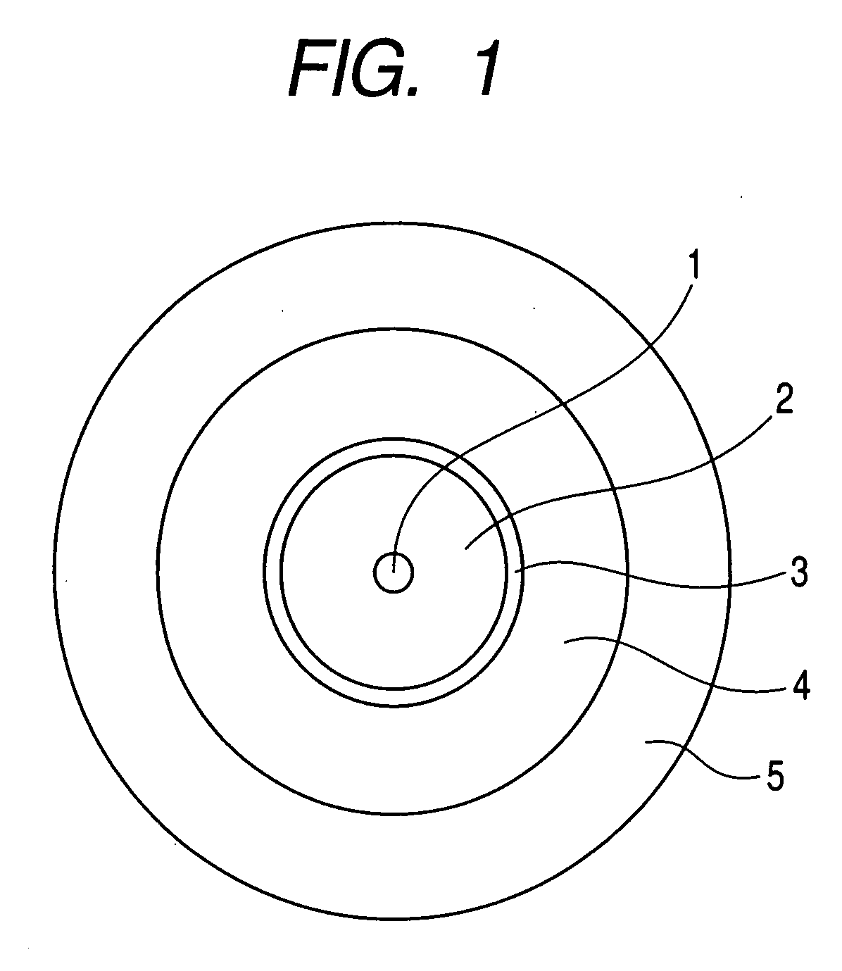
[0041]FIG. 1 is a cross-sectional schematic diagram showing one example of an optical fiber of the present invention. As illustrated in FIG. 1, the optical fiber of the present invention has a glass optical fiber which has a core 1, passing an optical signal, in a center portion and a cladding 2 in its outer periphery, a primary protective layer 3 made to coat the glass optical fiber, a secondary protective layer 4 applied on this primary protective layer 3, a third protective layer 5 applied to an outer periphery of this secondary protective layer 4, and is characterized in that glass transition temperature of the primary protective layer 3 is made to be higher than −20° C. and 10° C. or lower, glass transition temperature of the secondary protective layer 4 is made to be −10° C. or lower, and the glass transition temperature of the primary protective layer 3 is made higher than that of...


PUM

PropertyMeasurementUnit
glass transition temperatureaaaaaaaaaa

Abstract

The present invention provides an optical fiber in which composites constructing its coating are not complicated, so, there is also little constraint in view of production, and, moreover, delamination between a glass optical fiber and a primary layer, and a bubble in the primary layer hardly arise. The optical fiber of the present invention is an optical fiber which has a glass optical fiber which has a core 1, which passes an optical signal, in a center portion, and a cladding 2 surrounding this, a primary protective layer 3 made to coat the glass optical fiber, a secondary protective layer 4 applied on this primary protective layer 3, and a third protective layer 5 applied to an outer periphery of this secondary protective layer 4, wherein glass transition temperature of the primary protective layer 3 is made to be higher than −20° C. and 10° C. or lower, glass transition temperature of the secondary protective layer 4 is made to be −10° C. or less, and the glass transition temperature of the primary protective layer 3 is set higher than that of the secondary protective layer 4.

Description

BACKGROUND OF INVENTION[0001]1. Field of the Invention[0002]The present invention relates to an optical fiber, which has a highly reliable coating layer, in an optical fiber which transmits an optical signal.[0003]2. Related Background Art[0004]A common conventional optical fiber has structure of a core 1, which passes an optical signal, in a center portion as illustrated in FIG. 4, a soft primary layer 13 which is made to cover a glass optical fiber which includes a quartz glass which has a cladding 2 provided outside the core 1, and a hard secondary layer 14 which is further covered on this primary layer 13.[0005]Then, generally, an ultraviolet curing resin with 3 MPa or lower of Young's modulus is used for the above-mentioned primary layer 13, and an ultraviolet curing resin with 500 MPa or more of Young's modulus is used for the secondary layer 14, respectively.[0006]By the way, as for a polymeric material, physical properties change a lot with bordering on glass transition temp...

Claims


Application Information

Patent Timeline
Patent Type & Authority Applications(United States)
IPC IPC(8): G02B6/036
CPCC03C25/1065G02B6/4404G02B6/4402
Inventor NAKAJIMA, YASUOTANAKA, HIROKIARASHITANI, YOSHIHIROMOCHIZUKI, KOUJIOKADA, MITSUNORI
Owner FURUKAWA ELECTRIC CO LTD
Learn More