
Routing control system for l3vpn service network

a routing control system and service network technology, applied in the direction of data switching networks, electrical equipment, digital transmission, etc., can solve the problems of increasing the load of the routing system, the communication on a particular route is interrupted, and the routing server is processed. the effect of avoiding the impact of the other user network

Inactive Publication Date: 2010-02-25
HITACHI LTD
View PDF10 Cites 117 Cited by
  • Summary
  • Abstract
  • Description
  • Claims
  • Application Information

AI Technical Summary

Benefits of technology

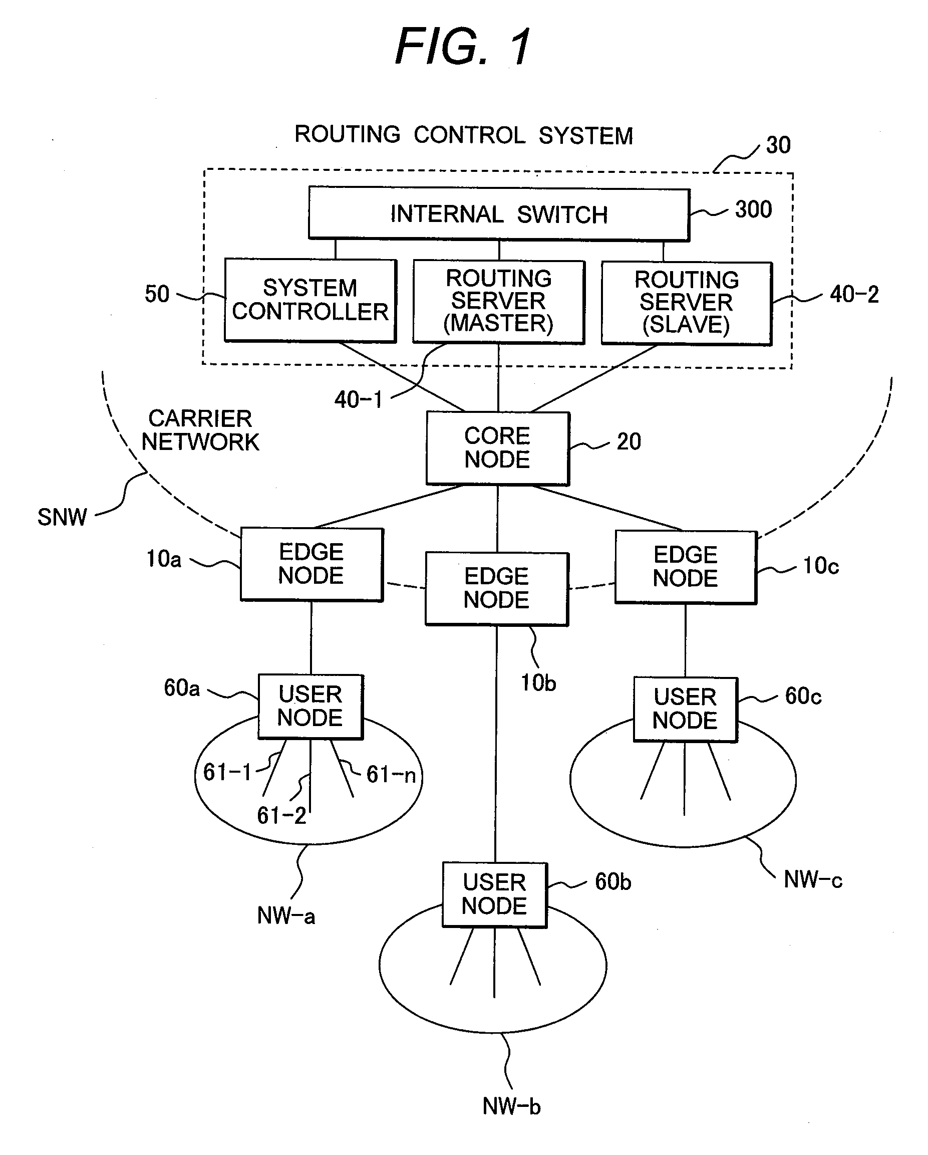
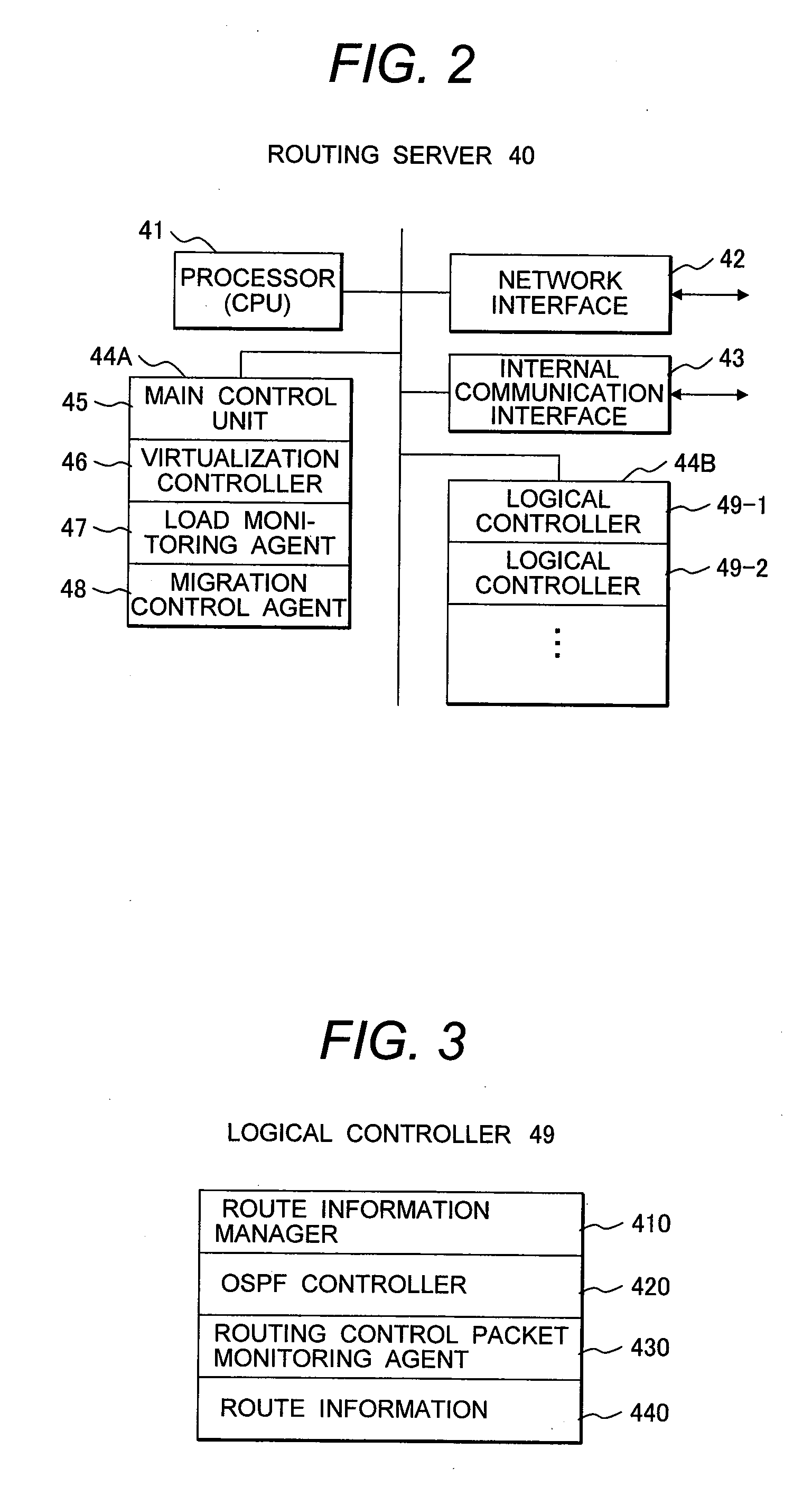
The present invention provides a routing control system for an L3VPN service network that prevents negative impact of increased routing control load for a particular user network on other user networks. The system includes a system controller, a master routing server, and a slave routing server. The system controller monitors the load state of the master routing server and migrates at least one logical controller from the master routing server to the slave routing server when the load state satisfies a predetermined condition. The slave routing server inherits routing control for a particular user network by activating the logical controller. This allows for efficient load balancing and prevents impact on other user networks.

Problems solved by technology

For example, if a malfunction occurs in one of communication nodes due to a coding error in a control program or shortage of memory capacity, this malfunction has an impact on routing control across the entire network system and may give rise to disrupted communication on a particular route according to circumstances.
However, when a plurality of user networks are connected to the L3VPN service network, the load of the routing system increases on account of various factors.
If a new customer joins in the L3VPN service, for example, the load of the routing system increases because of increasing in the number of networks to be controlled.
Further, if a loop has occurred in an Ethernet (registered trademark) serving as a user network due to incorrect cable connection, for example, there is a risk that a storm of routing control packets (routing requests) transmitted from routers in the user network may occur.
In this case, a burst of routing control packets not foreseen by the routing protocol will be transmitted into the routing system (route server), thereby causing a surge in the processing load on the route server.
Failure occurred in one of the routers in the user networks and bugs involved in routing control software running on the router may result in a burst of routing control packets.
Transmission of a burst of routing control packets from a user network by a malicious user also causes a surge in the load on the route server.

Method used


Image

  • Routing control system for l3vpn service network
  • Routing control system for l3vpn service network
  • Routing control system for l3vpn service network

Examples


second embodiment

[0143]FIG. 21 shows a second embodiment of a communication network to which the present invention is applied.

[0144]In the communication network of the first embodiment, since a plurality of routing servers 40-1 and 40-2 forming the routing control system 30 are connected by the internal switch 300 and located in the same IP segment, the slave routing server 40-2 can inherit the IP address of the migrated logical controller, without changing the route setting at the core node 20 or the internal switch 300.

[0145]In the communication network of the second embodiment, a plurality of routing servers 40-1 and 40-2 forming the routing system 30 are separately located at different sites distant from each other. In the communication network shown here, the system controller 50 is connected to a core node 20-1 in a control network 70-1, the master routing server 40-1 is connected to a core node 20-2 in a control network 70-2, and the slave routing server 40-2 is connected to a core node 20-3 ...


PUM


Abstract

A routing control system comprising a system controller and master and slave routing servers, wherein the master routing server includes a plurality of logical controllers, each of which performs routing control for each of the user networks, the system controller monitors a load state of the master routing server and migrates at least one of the plurality of logical controllers from the master routing server to the slave routing server when the load state has satisfied a predetermined condition, so that the slave routing server inherits routing control for a particular user network associated with the migrated logical controller.

Description

CLAIM OF PRIORITY[0001]The present patent application claims priority from Japanese patent application JP 2008-213250, filed on Aug. 21, 2008, the content of which is hereby incorporated by reference into this application.BACKGROUND OF THE INVENTION[0002](1) Field of the Invention[0003]The present invention relates to a routing control system and, more particularly, to a routing control system that is suitable for a Layer 3 Virtual Private Network (L3VPN) accommodating a plurality of customer or user networks.[0004](2) Description of Related Art[0005]An IP network system is composed of a plurality of communication nodes such as routers and switches. Each communication node is provided with a packet transport function unit for switching packets among a plurality of line interfaces and a control function unit connected to the packet transport function unit. Each communication node updates its route information table maintained thereon by communicating route information with the other ...

Claims


Application Information

Patent Timeline
Patent Type & Authority Applications(United States)
IPC IPC(8): H04L12/56H04L45/42H04L45/50H04L45/586
CPCH04L43/0817H04L43/16H04L45/64H04L45/50H04L45/586H04L45/00
Inventor OKITA, HIDEKI
Owner HITACHI LTD
Learn More