Worm-rack type transmission device
a transmission device and worm-rack technology, applied in the direction of lifting devices, friction gearings, gearings, etc., can solve the problems of unsuitable for extended distance travel, unsuitable for scroll-shaped teeth, machine tools in the mechanical industry, etc., to achieve relevant power transmission and strengthen the engagement
- Summary
- Abstract
- Description
- Claims
- Application Information
AI Technical Summary
Benefits of technology
Problems solved by technology
Method used
Image
Examples
first embodiment
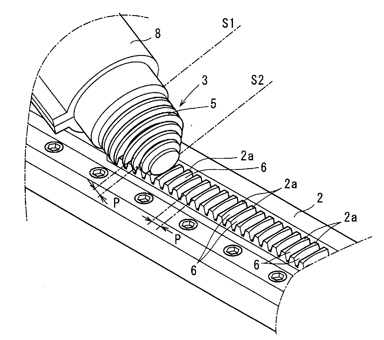
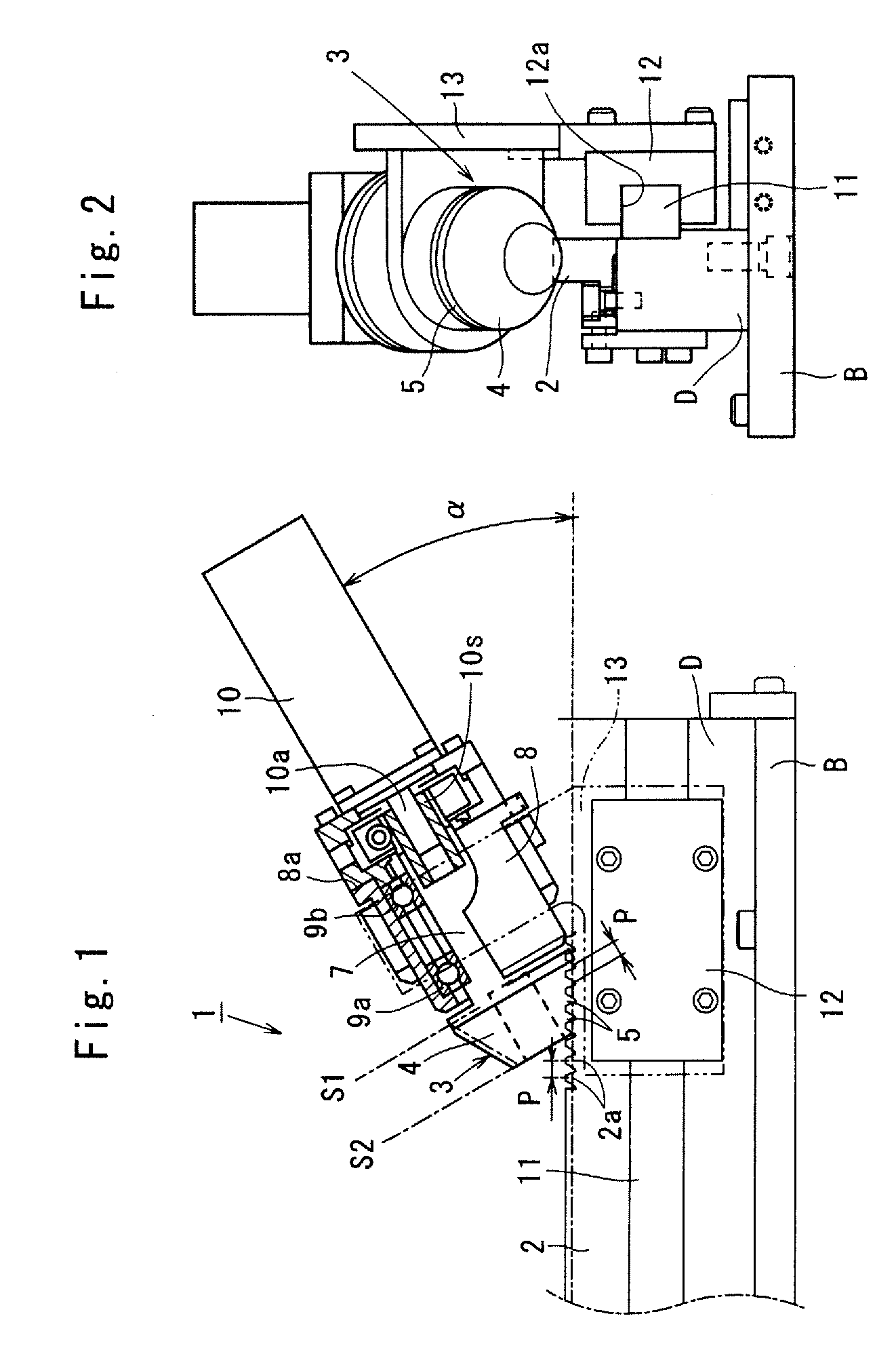
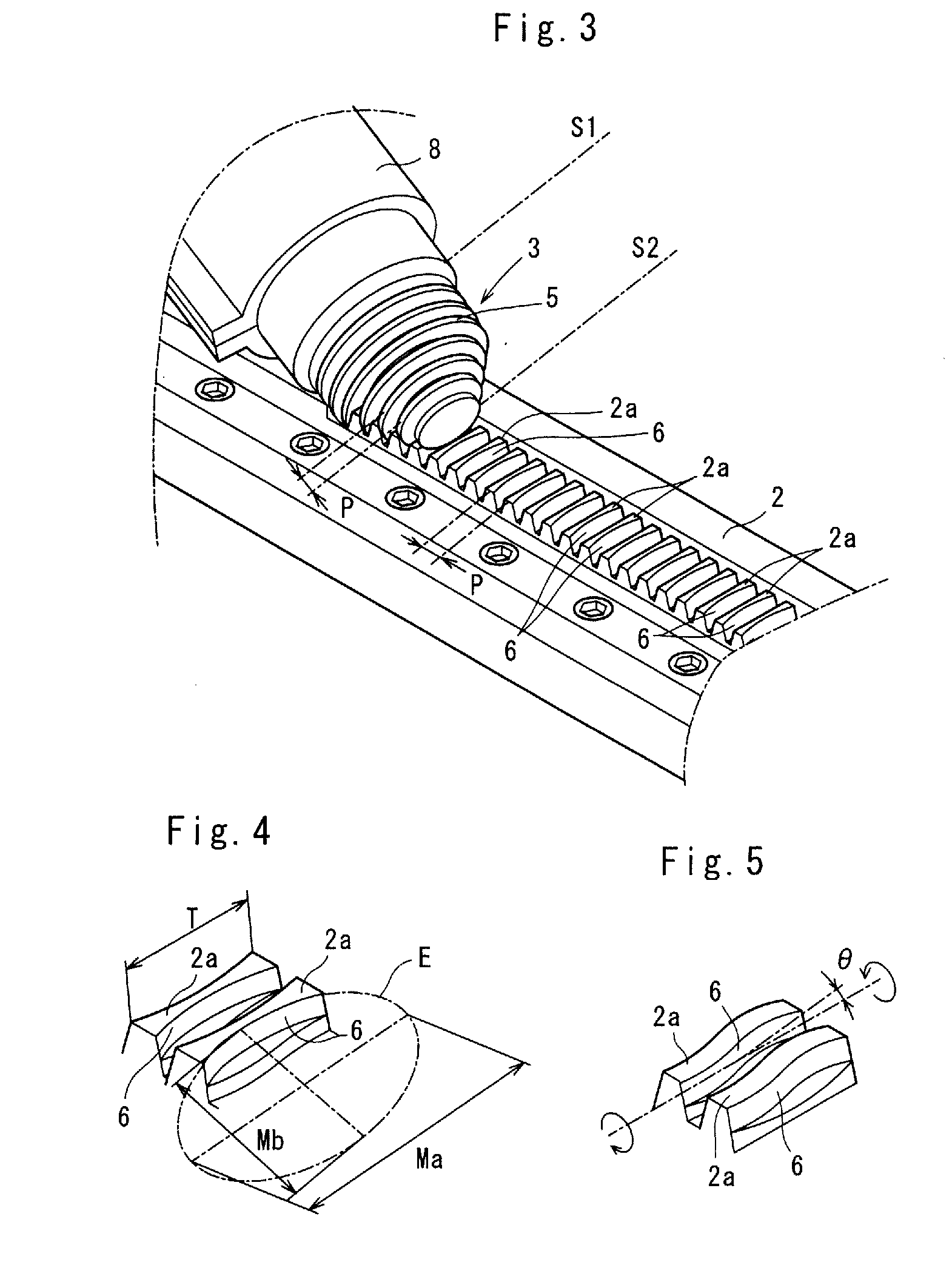
[0039]Referring to FIGS. 1 through 4 which show a worm-rack type transmission device 1 according to the invention, the worm-rack type transmission device 1 is used to a robot arm of a large-scaled machine tool installed in a floor of a machining factory.
[0040]In the worm-rack type transmission device 1, a linear rack 2 is made of a metallic material (e.g., iron or mild steel) substantially rectangular in cross section, and placed on a metallic beam D installed on a base plate B as shown in FIGS. 1, 2. The linear rack 2 is adapted to slide along a lengthwise direction of the metallic beam D, and having a number of rack teeth 2a at predetermined pitch intervals P. As a tooth profile, the rack teeth 2a are substantially trapezoidal in cross section.
[0041]A worm wheel 3 has a frustocone-shaped body 4 which is made of the metallic material (e.g., iron or mild steel). An outer surface of the frustocone-shaped body 4 integrally has a series of toothed streak 5 helically running therealong ...
second embodiment
[0058]FIG. 6 shows the invention in which the worm-rack type transmission device 1 is incorporated in carriage lift 14. The linear rack 2 is vertically set on a stand with worm wheel 3 placed within the carriage lift 14. The carriage lift 14 is used to carry goods and baggage, or used to send an operator (not shown) to work at a high elevation.
[0059]The carriage lift 14 has an accommodation box 17, a horizontal pallet 18 placed on the box 17 and hand rails 19a, 19ba vertically fixed to a right and left side of the pallet 18. Inside the box 17, the worm wheel 3, the housing 8 and the motor 10 are firmly placed. The motor 10 is connected to a power source outlet 16 by way of a conductive cord 15. In FIG. 6, the guide bar 11, the slider plate 12, the guide plate 13 are omitted for the purpose of convenience.
[0060]When a user U actuates a remote control device 20 with the goods, baggage or the operator laid on the pallet 18, the motor 10 is energized through an antenna 20a to rotate the...
PUM
 Abstract
Description
Claims
Application Information
 - R&D
- Intellectual Property
- Life Sciences
- Materials
- Tech Scout
- Unparalleled Data Quality
- Higher Quality Content
- 60% Fewer Hallucinations
Browse by: Latest US Patents, China's latest patents, Technical Efficacy Thesaurus, Application Domain, Technology Topic, Popular Technical Reports.
© 2025 PatSnap. All rights reserved.Legal|Privacy policy|Modern Slavery Act Transparency Statement|Sitemap|About US| Contact US: help@patsnap.com


