
Test Vessel, Test Strip, Test Kit, And Test Method

a test kit and test vessel technology, applied in the direction of analytical using chemical indicators, laboratory glassware, instruments, etc., can solve the problems of inaccurate determination, inaccuracy of determination, inaccurate determination, etc., to simplify and more accurate tests, and reduce the degree of sample exposure

Inactive Publication Date: 2010-02-25
RENESSELAER POLYTECHNIC INST +1
View PDF11 Cites 6 Cited by
  • Summary
  • Abstract
  • Description
  • Claims
  • Application Information

AI Technical Summary

Benefits of technology

[0028]According to the present invention, a test vessel that enables the reduction of the degree of exposure of samples to the external environment as well as the execution of simpler and more accurate tests such as the examination and diagnosis of samples can be obtained.
[0029]The test strip according to the present invention is suitably used when combined with the test vessel of the present invention, and by using them, the reduction of the degree of exposure of samples to the external environment as well as the execution of simpler and more accurate tests such as the examination and diagnosis of samples can be achieved.
[0030]According to the test kit of the present invention, the reduction of the degree of exposure of samples to external environment as well as the execution of simpler and more accurate tests such as the examination and diagnosis of samples can be achieved.
[0031]According to the test method of the present invention, the reduction of the degree of exposure of samples to external environment as well as the execution of simpler and more accurate tests such as the examination and diagnosis of samples can be achieved.

Problems solved by technology

However, when a pretreatment such as a suspension treatment and a filtration treatment is required while handling samples like stool and urine, operating procedures of such pretreatments may vary among different individuals which may lead to inaccurate determinations.
Moreover, when there is a technical variation among different individuals for bringing a sample fluid into contact with a test strip, this can also be a cause for inaccurate determinations.
When manually carrying out the dropwise addition of the sample extraction solution onto the test strip, it is possible that the procedures for bringing the test strip into contact with the sample may vary among different individuals, which may lead to inaccurate determinations.

Method used


Image

  • Test Vessel, Test Strip, Test Kit, And Test Method
  • Test Vessel, Test Strip, Test Kit, And Test Method
  • Test Vessel, Test Strip, Test Kit, And Test Method

Examples


first embodiment

Test Vessel

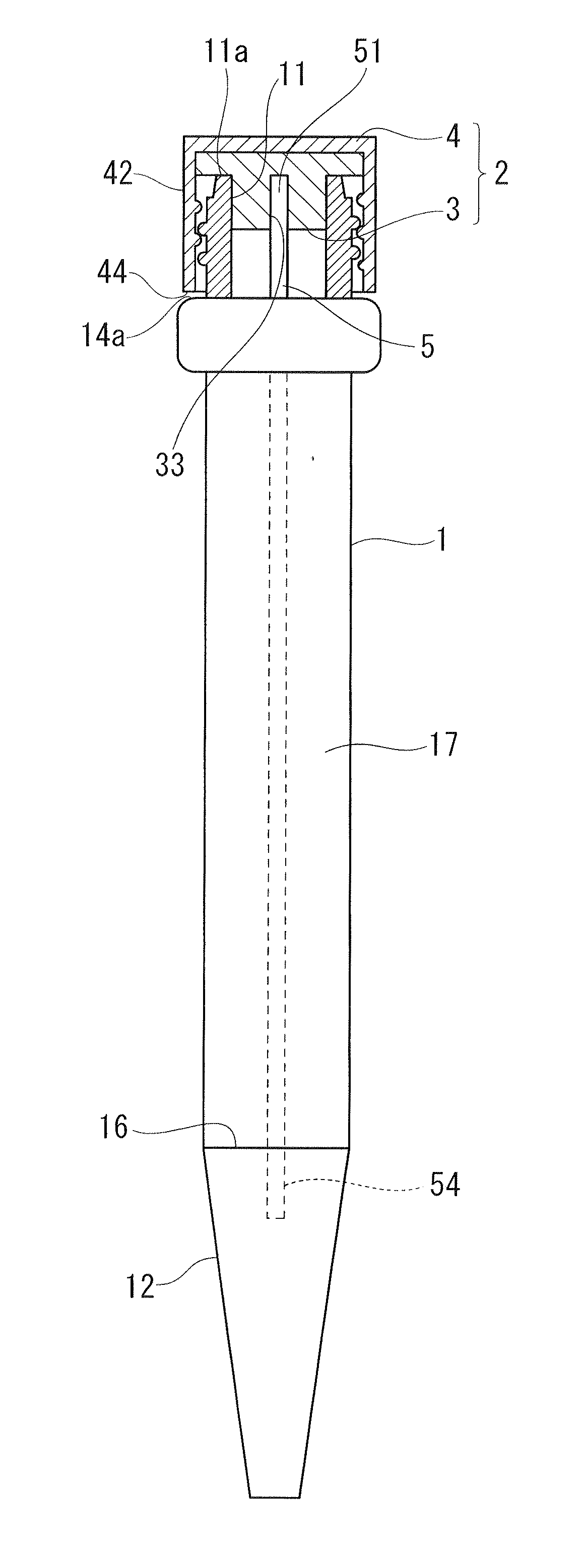
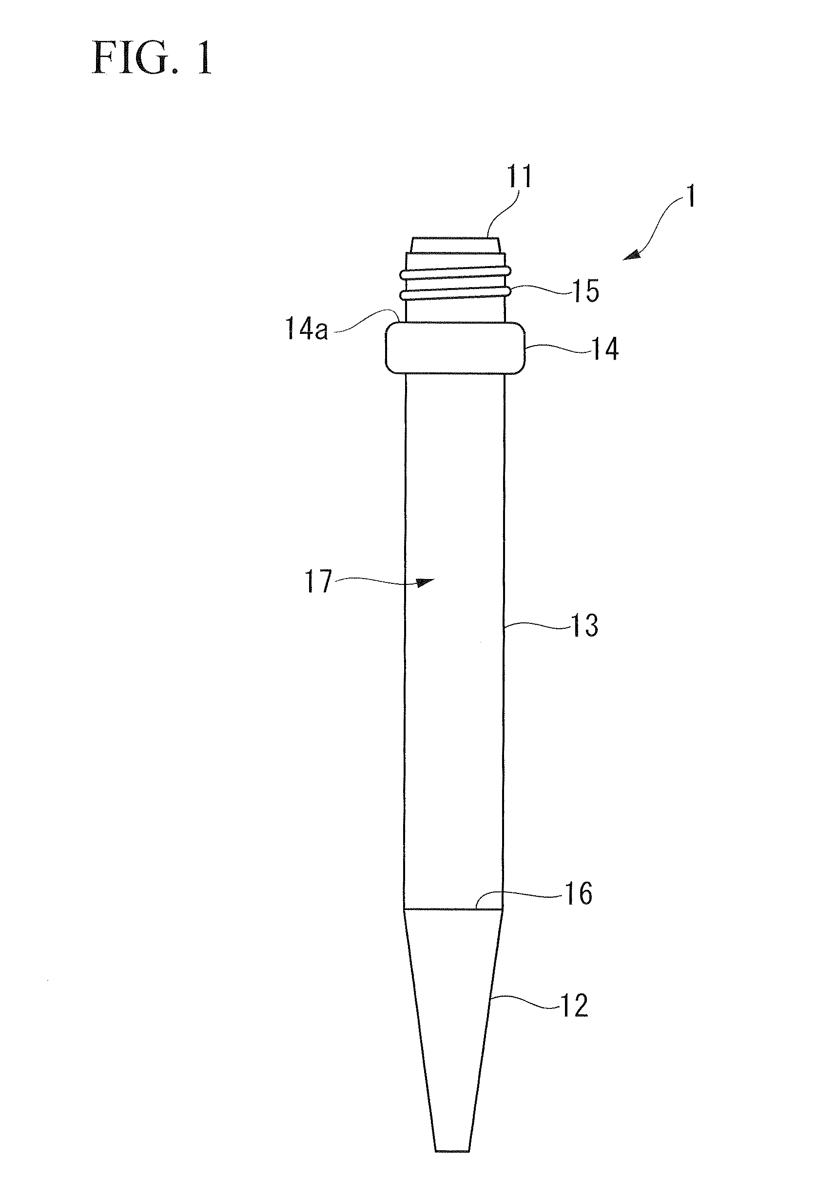
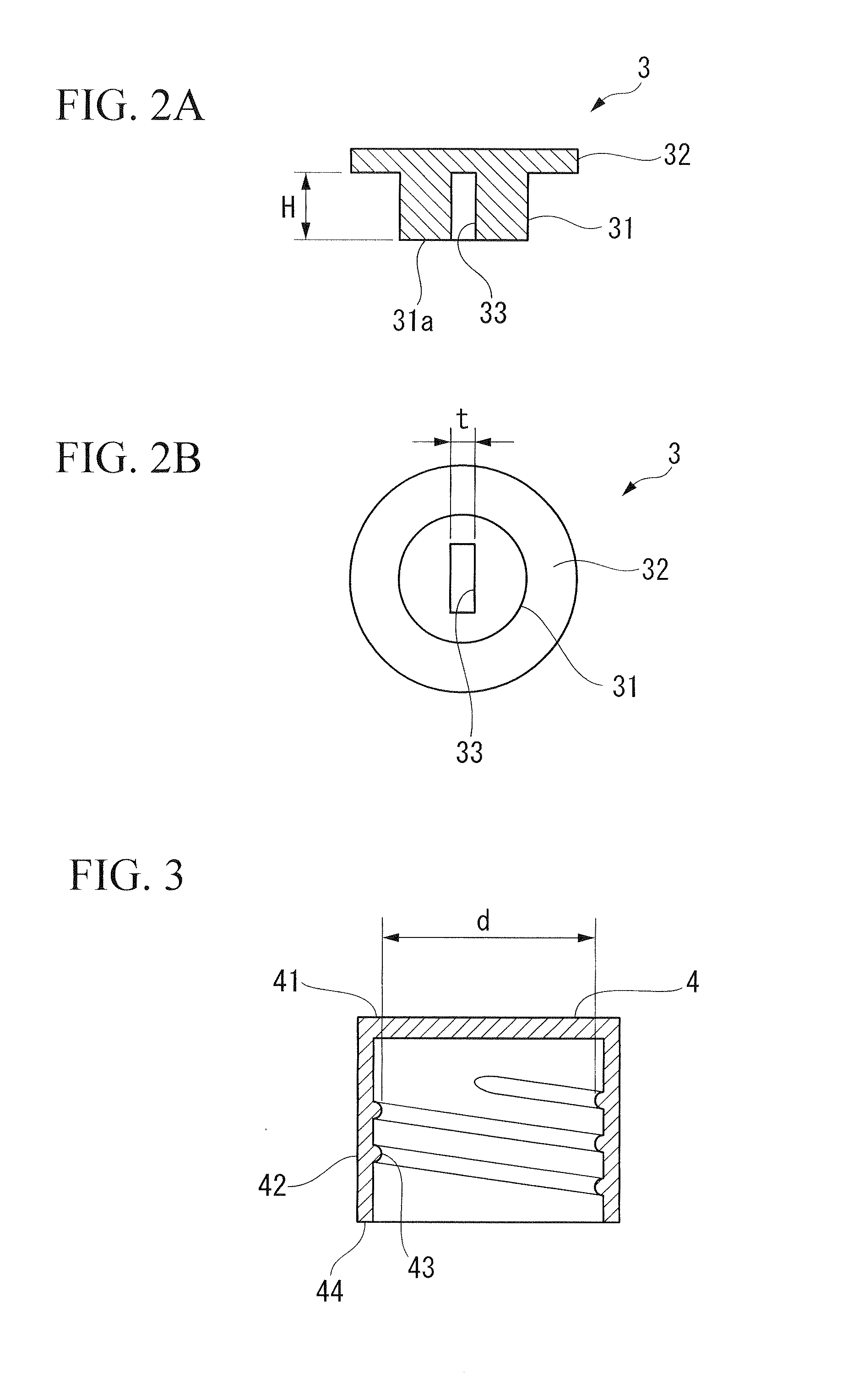
[0042]FIGS. 1 to 4 show a first embodiment of a test vessel according to the present invention and FIG. 1 is a front view of a vessel body 1. FIG. 2A is a cross sectional view of an inner packing 3 whereas FIG. 2B is a plan view of the inner packing 3 seen from the vessel body side. FIG. 3 is a cross sectional view of a cap 4. FIG. 4 is a partially cross sectional front view showing a state where a test strip 5 and a lid body 2 are set to the vessel body 1. A test vessel of the present embodiment is composed of the vessel body 1 and the lid body 2. The lid body 2 is composed of the inner packing 3 and the cap 4.

[0043]The vessel body 1 is formed of a bottomed hollow vessel having an opening 11 at its upper end. In the vessel body 1 of the present embodiment, a tapered top end section 12 that decreases in diameter towards the top end, a cylindrical barrel section 13, a swelling section 14 having an outer diameter greater than that of the barrel section 13, and a threaded se...

second embodiment

[0086]The shape of the inner packing is different between the first embodiment and the present embodiment.

[0087]FIG. 6 shows an inner packing 6 and FIG. 6A is a cross sectional view thereof whereas FIG. 6B is a plan view of the inner packing 6 seen from the vessel body side.

[0088]The inner packing 6 is composed of a disc-shaped flange section 62 and a cylinder-shaped convex section 61. The material of the inner packing 6 is the same as that in the first embodiment.

[0089]The outer diameter of the convex section 61 is formed so that it is somewhat larger than the inner diameter of the opening 11 of the vessel body 1. As a result, it is configured so that when the convex section 61 is inserted in the opening 11, the convex section 61 closely attaches to the inner wall of the opening 11 while being elastically deformed, thereby fluid-tightly sealing the opening 11 in a manner where the convex section 61 is attachable / detachable.

[0090]The outer diameter of the flange section 62 is formed...

modified example

[0094]As a modified example of the second embodiment, as shown in FIG. 7, a fitting hole 73 (test strip fixing section) of an inner packing 7 may be formed so as to penetrate a convex section 71 and a flange section 72.

[0095]In the present embodiment, the gripping section 50 of the test strip 5 is inserted into the fitting hole 73 of the inner packing 7, and the inner packing 7 is inserted in the opening 11 while being elastically deformed. Thereby, the outer peripheral surface of the convex section 71 closely attaches to the inner surface of the opening 11 and the inner surface of the fitting hole 73 closely attaches to the outer surface of the gripping section 50 of the test strip 5, as a result of which the opening 11 is sealed in a fluid-tight manner.

[0096]A non-penetrating type of fitting holes like the fitting hole 63 shown in FIG. 6 is preferable in view of easy setting of the end section of the immersion area 54 of the test strip 5 at a constant position while the test strip...


PUM

PropertyMeasurementUnit
lengthaaaaaaaaaa
lengthaaaaaaaaaa
outer diameteraaaaaaaaaa

Abstract

The present invention relates to a test vessel used in a test method having a step of immersing one end (54) of a test strip (5) in a sample fluid, the test vessel including a vessel body (1) having an opening (11) at an upper end thereof as well as a storage space (17) communicating with the opening (11) and in which the sample fluid is stored; a lid body (2) that seals the opening (11) of the vessel body (1) in an attachable / detachable manner; and a test strip fixing section (33) provided in the lid body (2) which fixes the other end of the test strip (5) in an attachable / detachable manner and holds the test strip (5) within the storage space (17) while sealing the opening (11) of the vessel body (1) with the lid body (2).

Description

TECHNICAL FIELD[0001]The present invention relates to a test vessel, a test strip, and a test kit that are suitable for a test method, and a test method which employs the same. In the method, one end of the test strip is immersed in a sample fluid and the determination is carried out by observing the visible changes occurred to the test strip.[0002]Priority is claimed on Japanese Patent Application No. 2007-310933, filed Nov. 30, 2007, the content of which is incorporated herein by reference.BACKGROUND ART[0003]Immunochromatography is a measuring method in which, when a sample fluid containing an antigen or an antibody flows over a membrane (a test strip) due to a capillary action, a color-labeled antibody that specifically reacts with the antigen or the antibody and a capture antibody form a complex with the antigen or the antibody, and the resulting coloration is visually observed.[0004]For example, commercial reagents for pregnancy tests measure the urinary human chorionic gonado...

Claims


Application Information

Patent Timeline
Patent Type & Authority Applications(United States)
IPC IPC(8): G01N1/10G01N31/22
CPCB01L3/5021B01L3/50825B01L2300/0663B01L2300/046B01L2300/0609B01L2300/042G01N33/53G01N33/50G01N33/48G01N1/00G01N33/525
Inventor KATSUMATA, NORIKO
Owner RENESSELAER POLYTECHNIC INST
Learn More