
Virtual metering

a virtual meter and meter technology, applied in the field of utility systems, can solve the problems of adversely affecting the accuracy of virtual meters, the general effect of virtual load monitoring, and the inability to determine the exact number of additional paths,

Active Publication Date: 2010-02-18
SQUARE D CO
View PDF1 Cites 44 Cited by
  • Summary
  • Abstract
  • Description
  • Claims
  • Application Information

AI Technical Summary

Benefits of technology

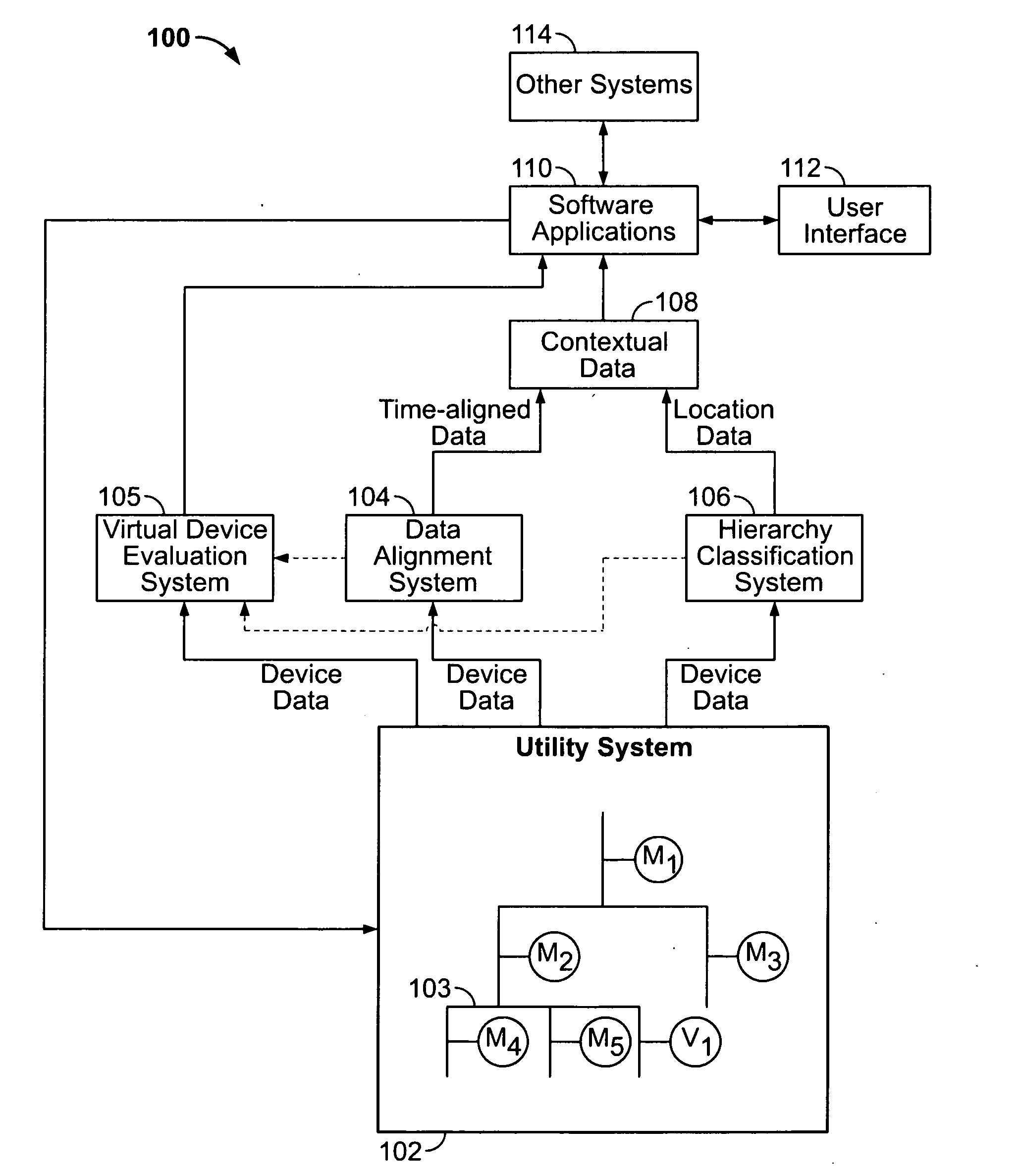
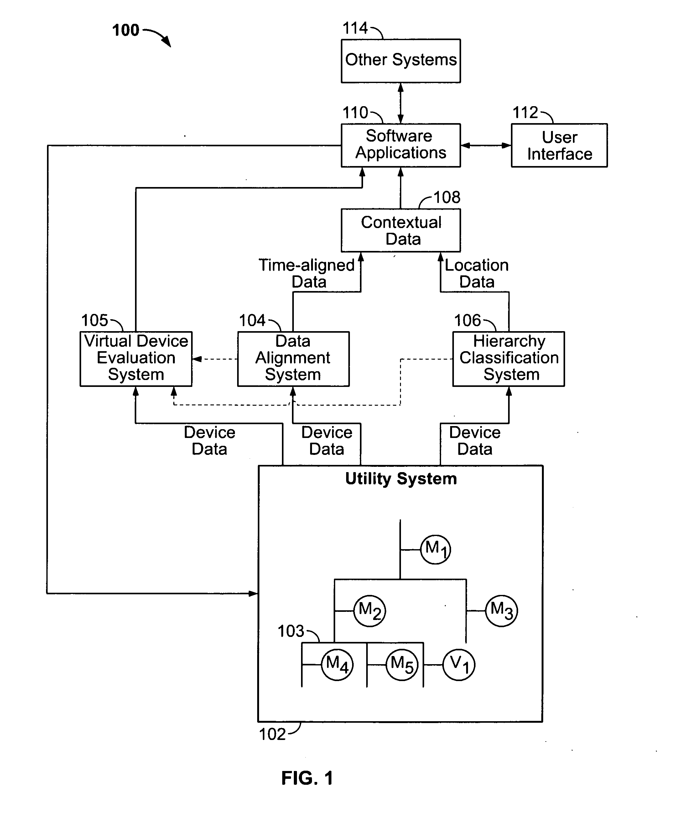
[0005]A virtual meter or virtual device is not a physical intelligent electronic device (IED). Virtual meters are essentially a logical mathematical deduction made from the combination of data measured in nearby physical IEDs. The law of conservation of energy states that energy may neither be created nor destroyed. Therefore, the sum of all the energies into and out of a system node must be zero. Using this principle, the energy flowing into a system bus must equal the energy flowing out of that system bus. FIG. 1 illustrates a simplified hierarchy of a utility system 102 that includes both real or physical meters (M1, M2, M3, M4, M5) and a virtual meter (V1). The energy flowing into the system bus 103 as measured by IED M2 is diverted into some unknown number of paths. In this example, the energy flowing through two of those paths is being measured by physical IEDs (M4 and M5). If the energy flow measured in IED M2 equals the energy flow measured in IEDs M4 and M5 collectively, then it can be deduced th

Problems solved by technology

Although determining the exact number of additional paths is not readily feasible (without visual inspection), it is possible to determine the aggregate energy flow through these additional unmetered paths in an ideal system.
There are two potential concerns that can arise which adversely affect the accuracy of virtual meters, and virtual load monitoring in general.

Method used


Image

  • Virtual metering
  • Virtual metering
  • Virtual metering

Examples


Embodiment Construction

[0035]Turning now to FIG. 1, an automated data integrated monitoring system 100 is generally shown. An electrical system 102 having multiple physical intelligent electronic devices (hereafter “IEDs”) designated by the letter M provides data from each IED M that is communicated to an automated data alignment system 104 and an automated hierarchy classification system 106. As used herein, an IED refers to any physical or real system element or apparatus with the ability to sample, collect, or measure one or more operational characteristics or parameters (characteristics and parameters are used interchangeably herein) of a utility monitoring system 102. The data is aligned automatically in temporal or pseudo-temporal context in the automated data alignment system 104 and produces data that is temporally aligned such that it represents the data when it was actually seen simultaneously by the monitoring devices M in the utility monitoring system 102. The hierarchy classification system 1...


PUM


Abstract

Methods for improving the accuracy of characterizing unmonitored paths or virtual meters in a utility system. The hierarchical arrangement of IEDs in the utility system is determined. Measured quantities of a characteristic of the utility being monitored are received and error-adjusted using statistical or absolute methods. The statistical method accounts for the mean and standard deviation associated with error measurements of the subject IED, and the absolute method uses the absolute value of the error measurement, expressed as a percentage, to produce ranges of measured quantities within an error tolerance. The differences between the error-adjusted quantities are analyzed to determine whether an unmonitored path exists, and if so, whether the virtual meter is consuming or supplying the utility. The order in which IEDs are read is determined so that a parent and its children are read in sequence to increase synchronicity of the received data and the virtual meter evaluation.

Description

FIELD OF THE INVENTION[0001]Aspects disclosed herein relate generally to utility systems, and, in particular, to methods for automatically improving the accuracy of identifying virtual monitoring devices in a utility monitoring system.BACKGROUND[0002]Because energy consumers cannot afford to install monitoring equipment and devices at every point of utilization within their facility, nearly every monitoring system has unmetered or unmonitored loads. In many cases these unmetered loads can account for a substantial portion of the customer's usage of a utility. Although the primary charter of monitoring equipment manufacturers is to provide utility consumers with useful and accurate information on the quality and consumption of a utility within their facility, a proper evaluation of these unmetered loads through the use of virtual meters is often overlooked in the manufacturers' product offerings.[0003]Many monitoring systems include a large number of physical intelligent electronic d...

Claims


Application Information

Patent Timeline
IPC IPC(8): G06F15/00
CPCG01D4/004Y04S20/322Y02B90/242G01R22/10Y04S20/30Y02B90/20
Inventor CARTER, RONALD W.BICKEL, JON A.HASAN, AMJAD
Owner SQUARE D CO
Learn More