
Display device and display method thereof

a display device and display method technology, applied in the field of display devices, can solve the problems of reducing luminance and transmittance, and achieve the effects of reducing luminance, excellent color reproducibility, and increasing luminance of image displays

Inactive Publication Date: 2010-02-11
SHARP KK
View PDF14 Cites 25 Cited by
  • Summary
  • Abstract
  • Description
  • Claims
  • Application Information

AI Technical Summary

Benefits of technology

[0036]According to the first aspect of the present invention, a first display mode where the gray scale value of a sub-pixel of at least one color is a predetermined value and a second display mode using all sub-pixels of four or more colors for gray scale display are provided. Selection of the display modes is made based on the intensity of outside light. Then, when the intensity of outside light is less than a reference intensity, image display is performed in the first display mode, and when the intensity of outside light is greater than or equal to the reference intensity, image display is performed in the second display mode. Hence, when the display device is used in a dark environment, by setting the predetermined value to decrease luminance, such image display that can obtain excellent color reproducibility is performed. On the other hand, when the display device is used in a bright environment, by using all sub-pixels to perform gray scale display, image display with increased luminance is performed. Accordingly, switching between image display where color reproducibility is given priority over luminance and image display where luminance is given priority over color reproducibility can be effectively performed according to the environment where the display device is used.
[0037]According to the second aspect of the present invention, when the first display mode is selected by the display mode selecting unit, a sub-pixel of at least one color is fixed to black display. Thus, when the display device is used in a dark environment, a well-defined image with deep colors is displayed.
[0038]According to the third aspect of the present invention, in a display device having a sub-pixel of white, as with the first aspect, switching between image display where color reproducibility is given priority over luminance and image display where luminance is given priority over color reproducibility can be effectively performed according to the environment where the display device is used.
[0039]According to the fourth aspect of the present invention, in a display device having a sub-pixel of yellow or cyan, as with the first aspect, switching between image display where color reproducibility is given priority over luminance and image display where luminance is given priority over color reproducibility can be effectively performed according to the environment where the display device is used.
[0040]According to the fifth aspect of the present invention, the gray scale value of a sub-pixel of a color other than three primary colors, red, green, and blue, is determined based on a gray scale value determination table. Hence, by minutely setting the gray scale value of a sub-pixel of a color other than the three primary colors, taking into account color reproducibility and luminance, more favorable image display is performed. In addition, by changing the values in the gray scale value determination table, color adjustment is easily performed.
[0041]According to the sixth aspect of the present invention, the gray scale values of sub-pixels of three primary colors, red, green, and blue, are also determined based on the gray scale value determination table. Hence, the gray scale values of the sub-pixels of the three primary colors can also be minutely set in advance and thus more favorable image display is performed.

Problems solved by technology

Meanwhile, when the colors of color filters are deepened to widen the color reproducibility range, transmittance decreases and thus luminance decreases.

Method used


Image

  • Display device and display method thereof
  • Display device and display method thereof
  • Display device and display method thereof

Examples


first embodiment

1. First Embodiment

1.1 Overall Configuration and Operation

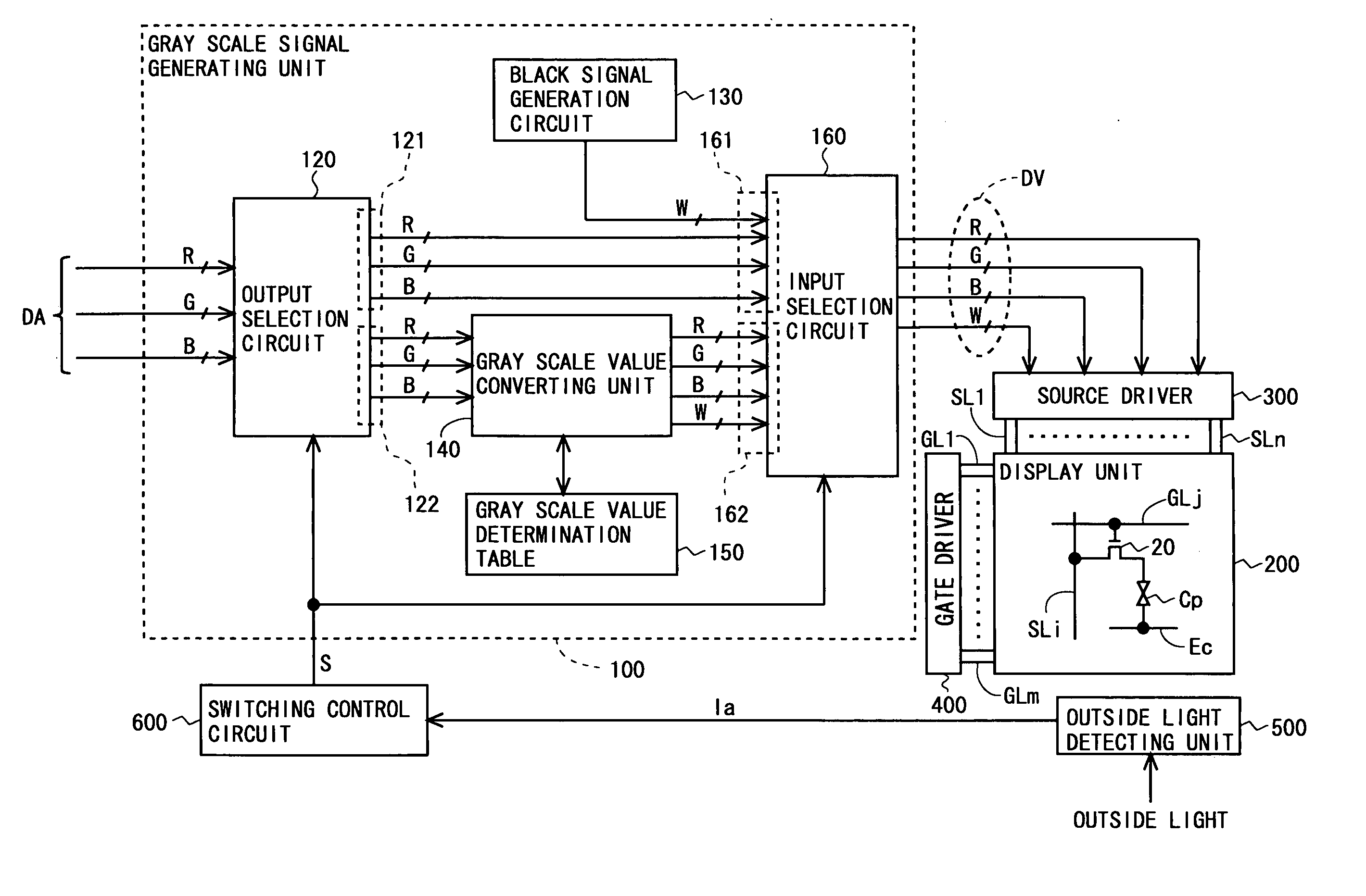
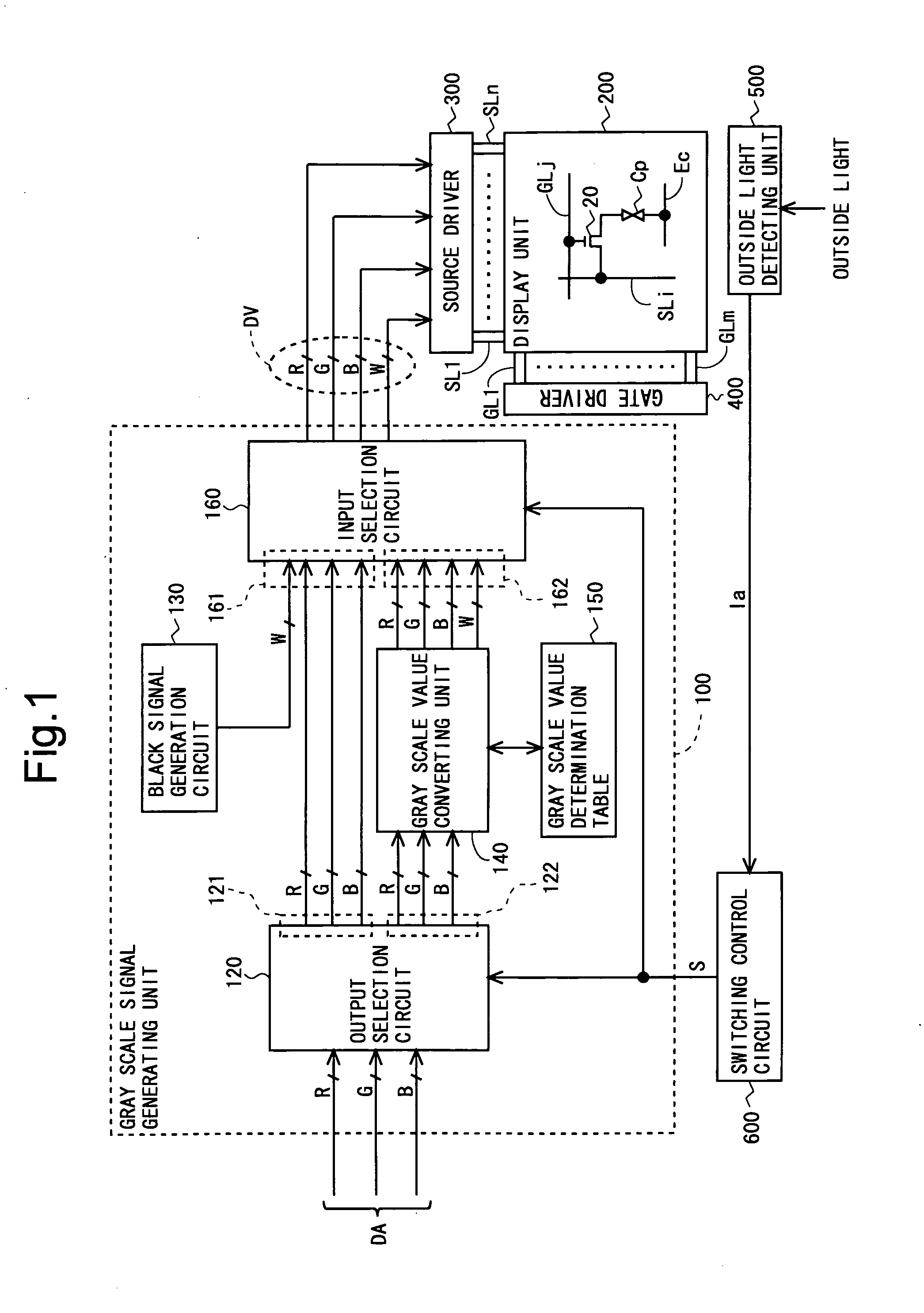
[0074]FIG. 1 is a block diagram showing an overall configuration of a liquid crystal display device according to a first embodiment of the present invention. The liquid crystal display device includes a gray scale signal generating unit 100, a display unit (display panel) 200, a source driver (video signal line drive circuit) 300, a gate driver (scanning signal line drive circuit) 400, an outside light detecting unit 500, and a switching control circuit 600.

[0075]The display unit 200 includes a plurality of (n) source bus lines (video signal lines) SL1 to SLn, a plurality of (m) gate bus lines (scanning signal lines) GL1 to GLm, and a plurality of (n×m) pixel formation portions respectively provided at intersections of the plurality of source bus lines SL1 to SLn and the plurality of gate bus lines GL1 to GLm. The pixel formation portions are arranged in a matrix to configure a pixel array. Each pixel formation portion forms ...

second embodiment

2. Second Embodiment

2.1 Overall Configuration and Operation

[0121]FIG. 11 is a block diagram showing an overall configuration of a liquid crystal display device according to a second embodiment of the present invention. In the present embodiment, unlike the first embodiment, an output selection circuit 120 is not provided in a gray scale signal generating unit 100. Hence, as shown in FIG. 11, digital image signals (RGB image signals) DA sent from an external source are provided to an input selection circuit 160 and a gray scale value converting unit 143. The input selection circuit 160 includes a first input terminal 167 for receiving a W image signal outputted from the gray scale value converting unit 143; and a second input terminal 168 for receiving a W image signal outputted from a black signal generation circuit 130. Also, the gray scale value converting unit 143 is configured to refer to a W gray scale value determination table 155 as shown in FIG. 8. To the gray scale value co...

third embodiment

3. Third Embodiment

3.1 Overall Configuration and Operation

[0133]FIG. 12 is a block diagram showing an overall configuration of a liquid crystal display device according to a third embodiment of the present invention. In the present embodiment, unlike the first embodiment, each pixel is configured by sub-pixels of three primary colors RGB and a sub-pixel of Y (yellow) as shown in FIG. 15C. In a gray scale signal generating unit 100 two gray scale value converting units (a first gray scale value converting unit 144 and a second gray scale value converting unit 145) are provided. In addition, in the gray scale signal generating unit 100 are provided an RGB gray scale value determination table 156 for the first gray scale value converting unit 144 to refer to and an RGBY gray scale value determination table 157 for the second gray scale value converting unit 145 to refer to. As shown in FIG. 13, in the RGB gray scale value determination table 156, a combination of the gray scale values ...


PUM


Abstract

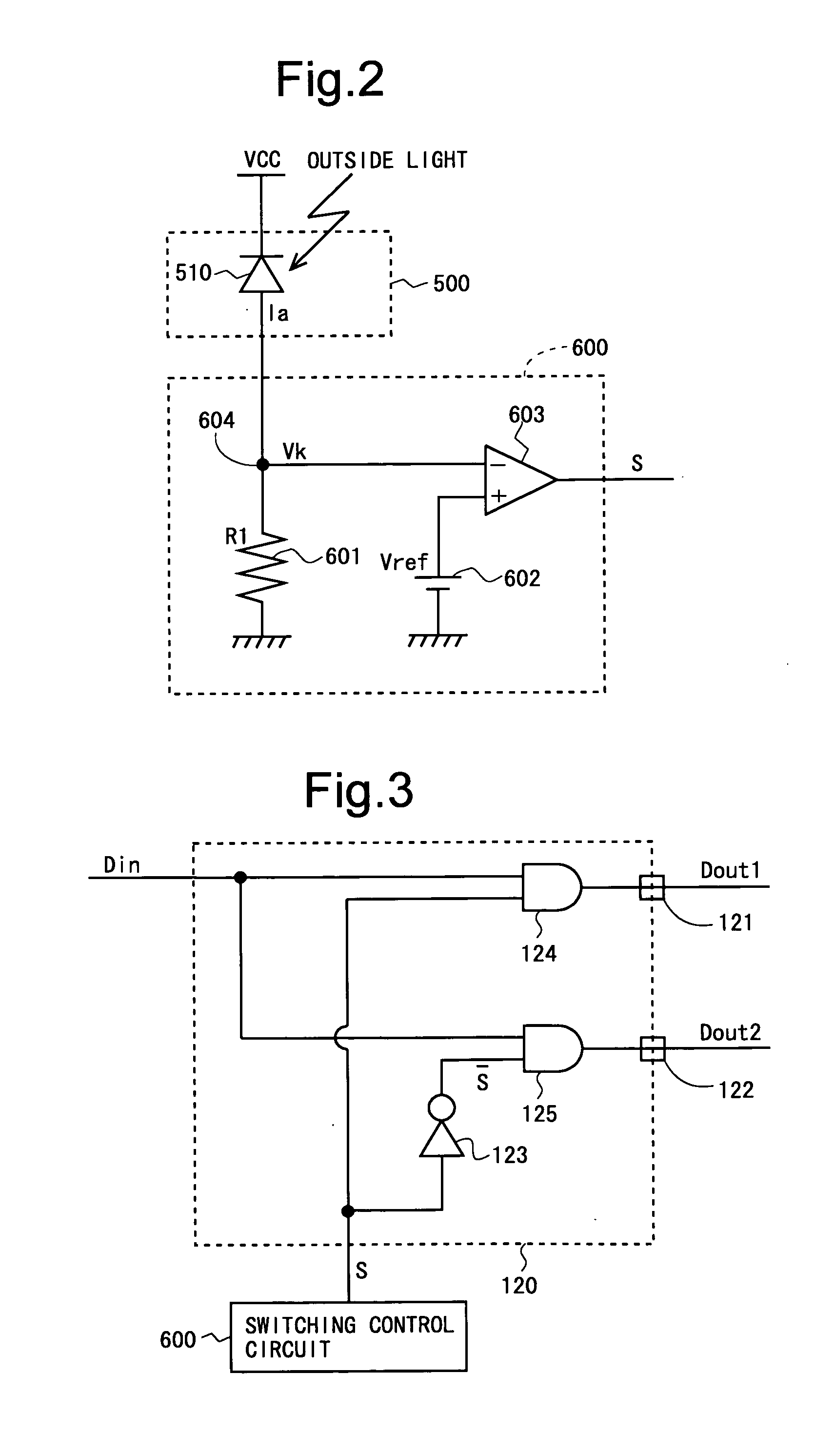
An object of the present invention is to provide a display device that achieves a balance between color reproducibility and luminance under the premise that the display device uses a display panel in which each pixel is configured by sub-pixels of four or more colors. An outside light detecting unit (500) outputs a current Ia according to the intensity of outside light. A switching control circuit (600) outputs a display mode selection signal (S) for selecting a display mode, based on the magnitude of the current (Ia). An output selection circuit (120) provides RGB image signals to an input selection circuit (160) when in a first display mode (when it is dark) and provides RGB image signals to a gray scale value converting unit (140) when in a second display mode (when it is bright). In the first display mode, a W image signal generated by a black signal generation circuit (130) is used as a gray scale signal (DV). In the second display mode, a W image signal generated by the gray scale value converting unit (140) referring to a gray scale value determination table (150) is used as a gray scale signal (DV).

Description

TECHNICAL FIELD[0001]The present invention relates to a display device, and more particularly to a display device including a display panel in which each pixel is configured by sub-pixels of four or more colors.BACKGROUND ART[0002]Conventionally, in liquid crystal display devices, color filters of three colors, red, green, and blue (RGB), are used to perform color image display. In such liquid crystal display devices, as shown in FIG. 15A, one pixel is configured by pixels of three colors, red, green, and blue (each pixel is referred to as a “sub-pixel”). By controlling the transmittance on a sub-pixel-by-sub-pixel basis, a desired color is displayed in each pixel. In recent years, there has been an increasing demand for widening the color reproducibility range (increasing color reproducibility) in such liquid crystal display devices. Also, occasions where liquid crystal display devices such as portable electronic devices are used outdoors have increased. Because of this, there has ...

Claims


Application Information

Patent Timeline
Patent Type & Authority Applications(United States)
IPC IPC(8): G09G5/10G06F3/038
CPCG09G3/3648G09G2320/0242G09G2340/06G09G2360/144
Inventor YOSHIDA, KEISUKENAKAJIMA, MUTSUMI
Owner SHARP KK
Learn More