Backpack frame system

Active Publication Date: 2010-02-11
MYSTERY RANCH
View PDF23 Cites 44 Cited by
  • Summary
  • Abstract
  • Description
  • Claims
  • Application Information

AI Technical Summary

Benefits of technology

[0012]In still another aspect of the invention, the hip belt has a generally diagonal fold seam in each side portion thereof allowing a substantial portion of the hip belt to be folded upwardly generally along the membrane and vertical support members. This folding action significantly reduces the front to rear “thickness” taken up by the backpack. In one arrangement, the hip belt is attached with the sleeves of left and right side outermost vertical support members so that fitting of the hip belt to a user causes such vertical support members to conform generally to the user's body profile.
[0013]Many advantages are provided by the backpack frame system and various other components of the invention that form a backpack. The latticework of vertical and horizontal semi-rigid support members provides active stabilizing of loads attached to the fram

Problems solved by technology

One drawback of the rigid frame design is that forces generated by an impact incident on the attached pack bag or the frame itself create stresses that tend to remain concentrated at either (1) the region of impact, (2) in the pack bag itself, or (3) at the associated connection points of the pack bag with the frame.
For example, because of the rigid nature and lack of give of the typical external frame under force loading, loads on the pack bag must often generate a high level of tension on the pack bag material before appreciable transferring of the loads to the frame occurs.
When an impact is severe, the locations of stress concentration tend to tear or fracture, and because pack bag material is not as strong as the rigid frame material, the bag may rip open and scatter the contents that were held therein.
Such connections are prone to fractures and tearing when the frame is under stress.
Another disadvantage of external frame backpacks is the tendency for such packs to be unstable relative to internal frame packs because the load is usually placed laterally farther away from the user's center of gravity, a situa

Method used


Image

  • Backpack frame system
  • Backpack frame system
  • Backpack frame system

Examples


Embodiment Construction

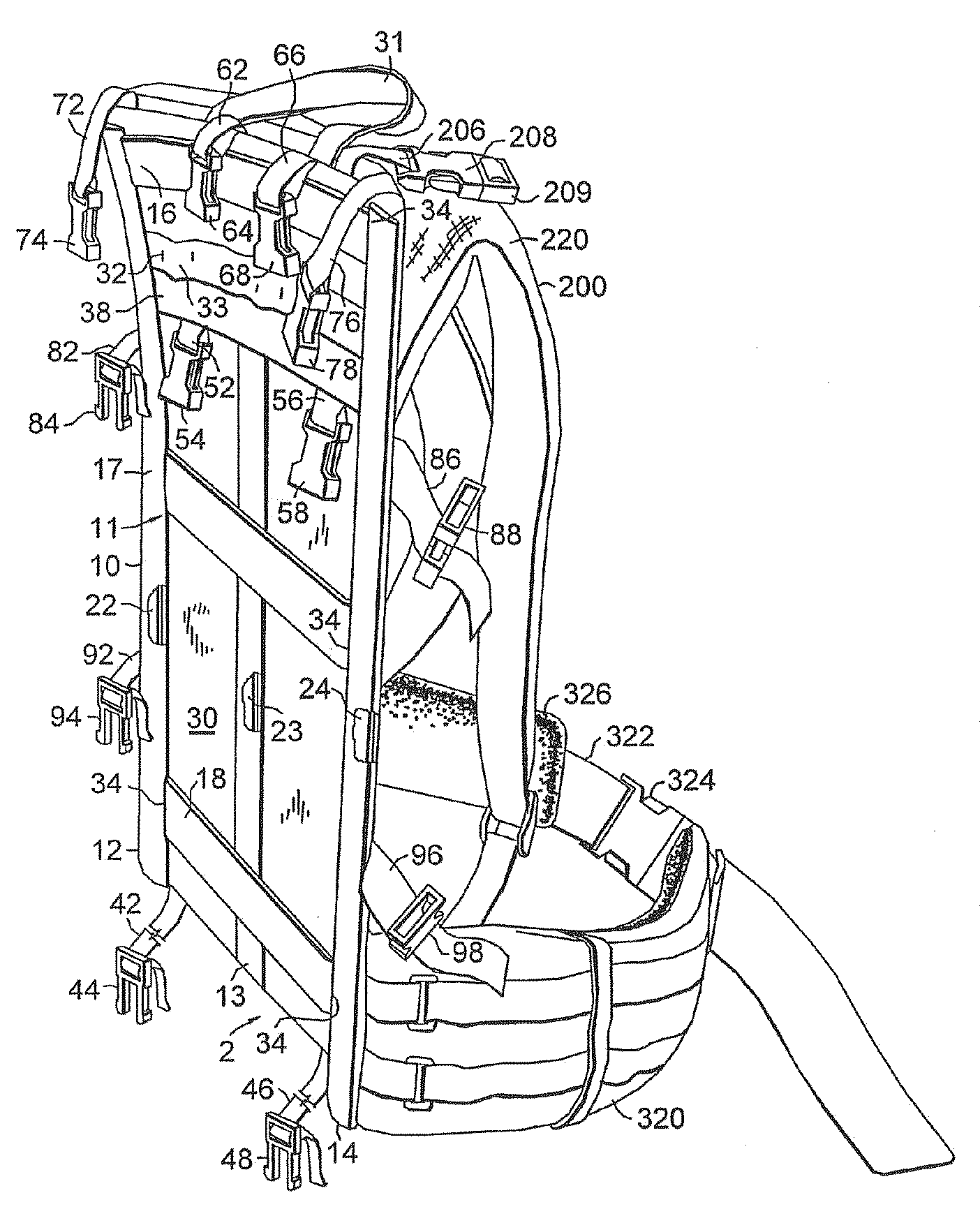
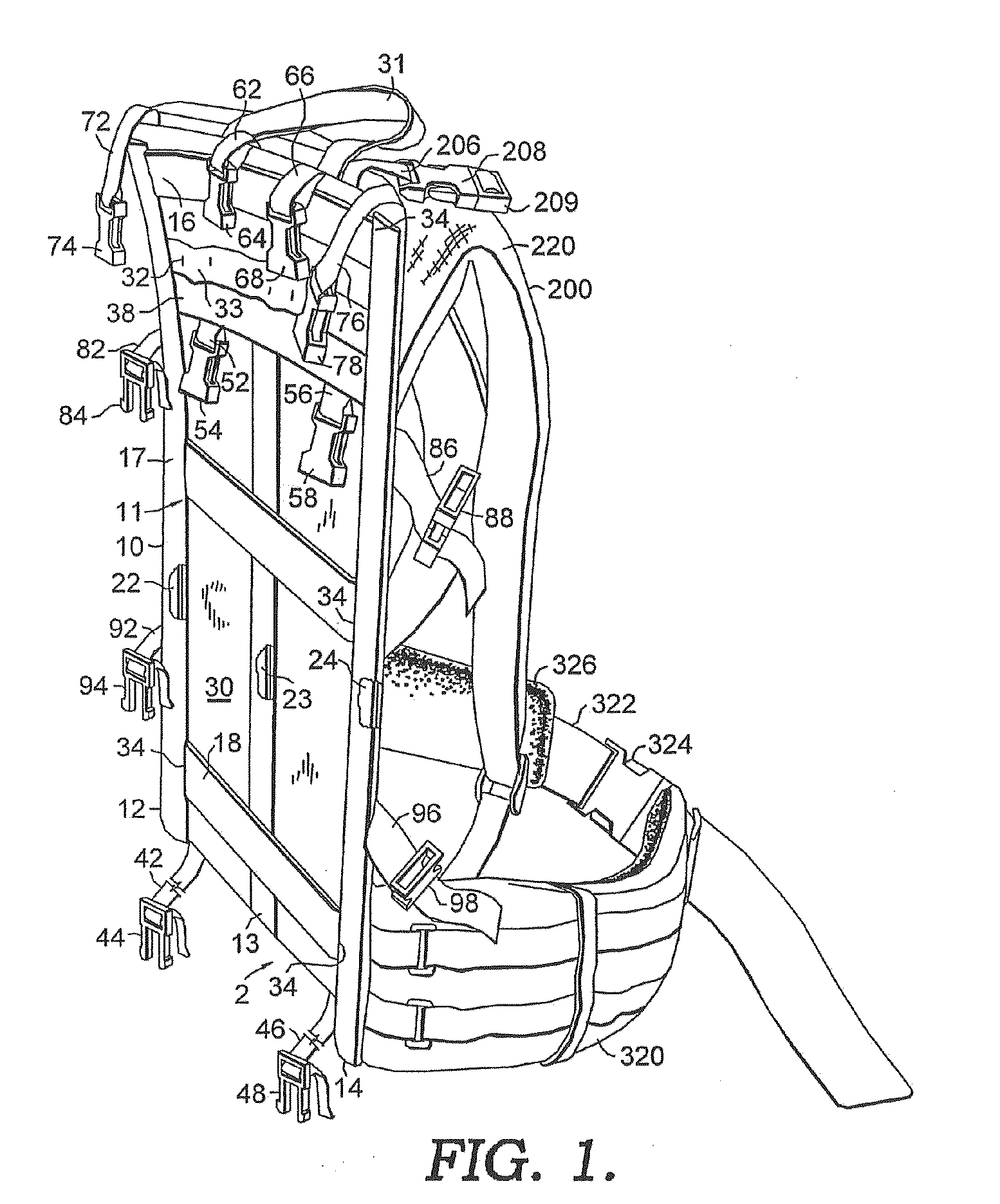
[0034]Referring now to the FIGURES in greater detail, and initially to FIG. 1, a backpack frame system (“frame system”) is designated by the reference numeral 10. The frame system 10 includes a base frame assembly 11 coupled with a hip belt 320 and a shoulder strap assembly 201 with shoulder straps 220 and yoke 200 to form a backpack that may be worn by a user to transport various contents. The description of pack frame system 10 will use terms such as vertical and horizontal. These terms are used to describe the parts when the pack frame system 10 is in its normal upright orientation.

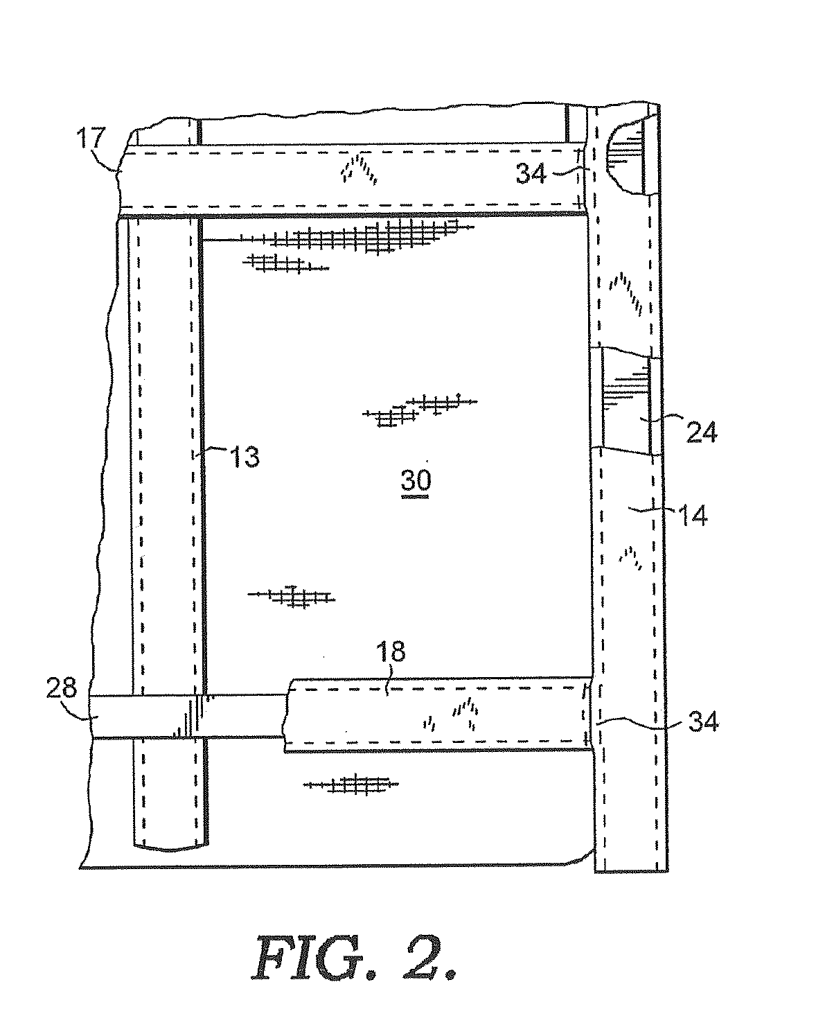
[0035]With additional reference to FIGS. 2, 3(a)(b), 4(a)(b) and 5, the base frame 11 includes a latticework of horizontally and vertically oriented semi-rigid support members or frame stays 22, 23, 24, 26, 27, and 28 that are encased in sleeves 12, 13, 14, 16, 17, and 18, respectively, and held in place by a membrane 30 forming various generally rectangular arrays of stays. Each of the frame sleeves 1...


PUM

PropertyMeasurementUnit
Angleaaaaaaaaaa
Flexibilityaaaaaaaaaa
Areaaaaaaaaaaa

Abstract

The present invention involves the provision of a backpack frame assembly and associated load carrying devices. The backpack frame includes a plurality of stays having flexible joints therebetween. A membrane is secured to certain of the stays and helps resist flexing of joints between adjacent stay end portions. Load carrying devices may be provided and are releasably mounted to the frame assembly. The distance between the assembly's shoulder straps and hip belt can be adjusted to accommodate user's having different torso lengths by using an adjuster sheet to separate hook and look members attaching a shoulder strap assembly to a frame assembly. The adjuster sheet can operate as a support element when not operating as an adjuster. The adjuster sheet can be constructed of a laminated composite material and include reinforcing ribs formed therein.

Description

CROSS-REFERENCE TO RELATED APPLICATIONS[0001]This Application is a Continuation-in-Part of and claims priority to U.S. application Ser. No. 10 / 907,087 filed Mar. 18, 2005 to Dana Wright Gleason Jr. entitled Backpack Frame System, currently pending, the entire disclosure of which is incorporated herein by reference.BACKGROUND OF INVENTION[0002]Backpacks have been used for many years to carry a given load of contents on the back of a user. Modern backpack designs configured to carry moderate to large loads (in terms of weight and / or bulk) usually fall into one of two categories: external frame backpacks and internal frame backpacks. Both internal and external frame backpacks have a waist or hip belt and a yoke. The hip belt is designed to transfer a substantial amount of the weight of the backpack and contents from rigid or semi-rigid supports of the backpack to the hips of the backpack user. The yoke is primarily designed to stabilize the backpack load and more properly position port...

Claims


Application Information

Patent Timeline
IPC IPC(8): A45F3/08A45F3/04
CPCA45F3/06A45F3/08A45F3/10A45F3/12Y10T29/49716A45F2003/122A45F3/047Y10S224/9018A45F2003/045
Inventor GLEASON, JR., DANA W.
Owner MYSTERY RANCH
Why Eureka
Try Eureka