
Massage Chair Servo

a servo and massage chair technology, applied in the field of massage chairs, can solve the problems of poor compatibility, poor massage effect, unstable movement, etc., and achieve the effect of reducing overhead, effective resulting massage, and convenient connection

Inactive Publication Date: 2010-02-04
FU WEI
View PDF10 Cites 28 Cited by
  • Summary
  • Abstract
  • Description
  • Claims
  • Application Information

AI Technical Summary

Benefits of technology

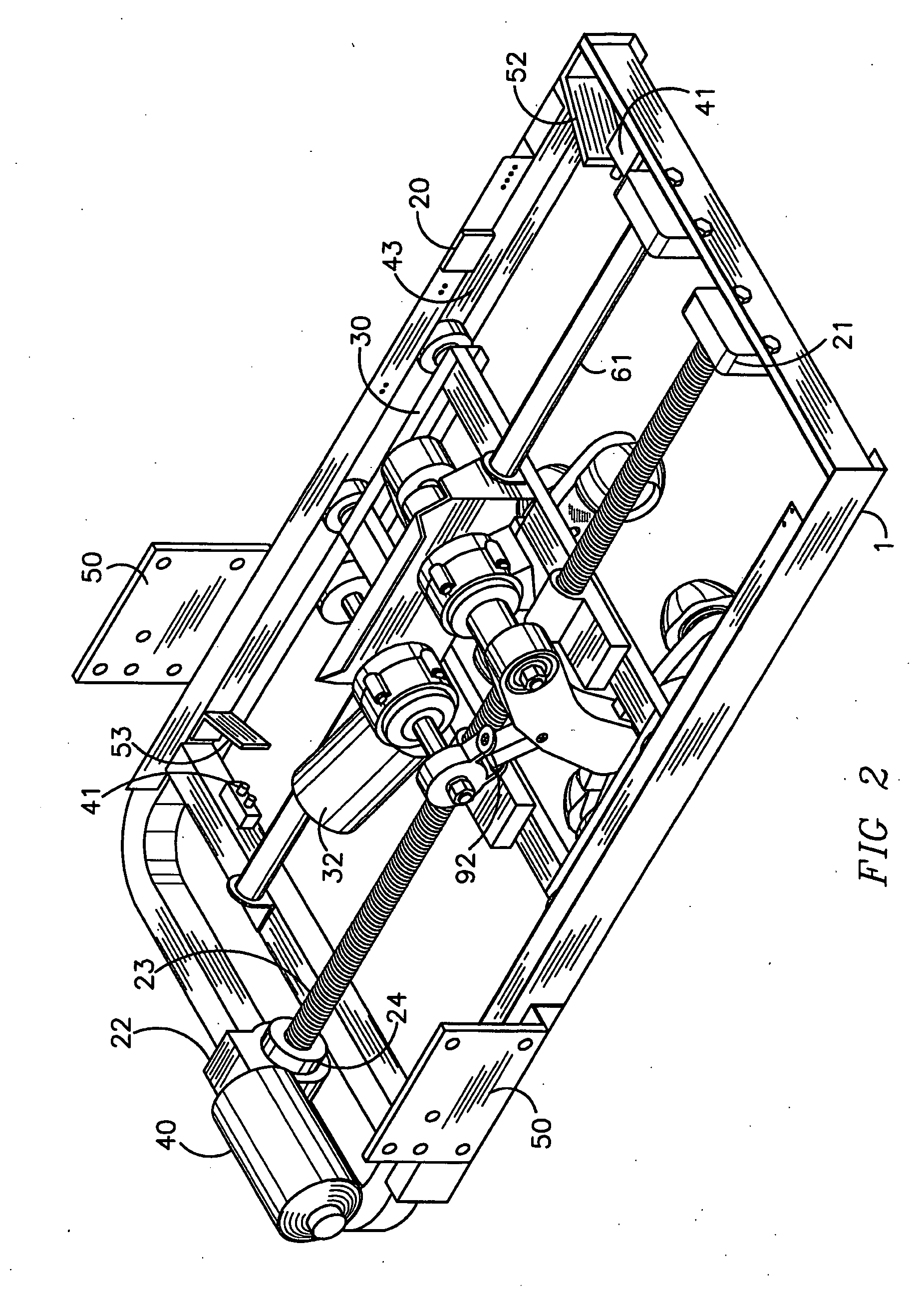
[0008]The sliding rack is coupled to various motor brackets, the screw drive, a positioning stabilizer bar, a driving block, a screw drive stop block, and a plurality of massaging wheels. The massaging wheels of the present invention incorporate “wave” indentations to provide for kneading massage motions similar to a hand massage and yet provide for smooth rolling resistance.
[0027]The advantages of this patent is its wide range of massage area, selective massage spots of a user's choice, smooth massaging movement, thereby creating an effective massage result.

Problems solved by technology

The existing massage chair frames and servo assembly racks presently in the market now, when in use, have problems of poor adaptation to the multiplicity and variety of chairs on the market, thereby causing unstable and wobbling in movement and creating a poor massage effect.
The existing massage chair frames and servo assembly racks on the market today have a number of problems such as: poor compatibility in installation causing very shaky movements during operation, and the effect of leaving a user with a massage feeling too far remote from the natural, relaxing and pleasant contour of real hand massages.
This is due to the inconvenient connection and positioning of these massage chair frames with respective massage chairs on the market.
This is in addition to the improper design of the massage parts and instability in connections and functions thereby leaving only a small area of effective massage for which to comfort a user.

Method used


Image

  • Massage Chair Servo
  • Massage Chair Servo
  • Massage Chair Servo

Examples


Embodiment Construction

[0043]Detailed descriptions of the preferred embodiment are provided herein. It is to be understood, however, that the present invention may be embodied in various forms. Therefore, specific details disclosed herein are not to be interpreted as limiting, but rather as a basis for the claims and as a representative basis for teaching one skilled in the art to employ the present invention in virtually any appropriately detailed system, structure or manner. Referring to the drawing figures, like reference numerals designate identical or corresponding elements throughout the several figures.

[0044]In accordance with a preferred embodiment of the invention, there is disclosed Within FIG. 1, a front, right and bottom view with a massage chair servo main rack (1) massage chair servo frame body (51), there is a sliding rack assembly (30), screw drive (60), positioning stabilizer bar (61), various stop switches (41), roller wheel assemblies (80), upper percussion motor assembly (31), lower pe...


PUM


Abstract

This new invention is a frame and servo assembly for attaching to massage chair seats manufactured without an existing servo assembly. It includes a frame body, on which there is sliding rack, a screw drive, a positioning stabilizer bar, and a connecting plate. The sliding rack is coupled to various motor brackets, the screw drive, a driving block, a screw drive stop block, and a plurality of wave shaped massaging wheels. The various motor brackets are coupled to two motors. One of the motors utilizes an axle with an off-center axis on both ends. There are multiple connecting brackets installed on the off-center axle, with wheel brackets installed at the end of the connecting brackets. Various “wave” shaped wheels at the end of the wheel brackets aid to simulate the natural feel of human hand joint movements to a user. At the two ends of the additional motor assemblies are bases for joint assemblies. These joint bases are connected to the connecting brackets via connecting joints. The wheels are located on the two ends of the sliding rack. The positioning stabilizer bar is affixed inside the frame body for stability.

Description

BACKGROUND OF THE INVENTION[0001]1. Field of the Invention[0002]This present invention relates to the field of massage chairs and specifically to a multi-functioning massage chair frame and servo assembly.[0003]2. Brief Description of the Related Art[0004]The existing massage chair frames and servo assembly racks presently in the market now, when in use, have problems of poor adaptation to the multiplicity and variety of chairs on the market, thereby causing unstable and wobbling in movement and creating a poor massage effect.[0005]The existing massage chair frames and servo assembly racks on the market today have a number of problems such as: poor compatibility in installation causing very shaky movements during operation, and the effect of leaving a user with a massage feeling too far remote from the natural, relaxing and pleasant contour of real hand massages.[0006]This is due to the inconvenient connection and positioning of these massage chair frames with respective massage cha...

Claims


Application Information

Patent Timeline
IPC IPC(8): A61H7/00
CPCA61H15/00A61H2015/0028A61H2205/081A61H2201/1654A61H2201/1669A61H2201/0149A61H15/0078
Inventor FU, WEI
Owner FU WEI
Learn More