
Method for low-severity gasification of heavy petroleum residues

a petroleum residue and gasification method technology, applied in the direction of combustible gas production, combustible gas purification/modification, hydrogen separation using liquid contact, etc., can solve the problem of refractory present, vanadium may also be a problem, and the cost of heavy oil extraction is therefore significantly dependent on the cost of steam produced

Active Publication Date: 2010-02-04
ENERKEM INC
View PDF10 Cites 41 Cited by
  • Summary
  • Abstract
  • Description
  • Claims
  • Application Information

AI Technical Summary

Benefits of technology

[0024]Other objects, advantages and features of the present invention will become more apparent upon reading of the following non-

Problems solved by technology

The cost of the heavy oil extraction is thus significantly dependent on the cost of the steam produced.
However, the presence of sulfur, nitrogen and metals (V and Ni for example) in these feedstocks require extensive treatment of the large amount of flue gases generated during combustion to lower particulate and pollutant emissions to below regulatory levels.
The presence of vanadium may also be a problem for the refractory present in the boilers used for the combustion which typically operate at high temperatures.
Indeed, in an oxidative medium, V2O5 tends to form, which compound has a melting point of 690° C., and to readily create deposits on the refractory walls of combustion boilers, which causes operational problems with time on stream.
In addition, combustion does not permit an easy and economical recovery of CO2.
However, natural gas pricing is subject to market fluctuations which inevitably influence the heavy oil extraction costs.
However, such high temperatures also imply rather high operational costs and require large scale-ups (about 100,000 bbl per day and more) to absorb the costs.
Such low severity configuration has not been considered satisfactory for carbonaceous matrices such as petcoke due to the low reactivity of the carbon structures present in petcoke.
However, such a gasification process still has to be developed.

Method used


Image

  • Method for low-severity gasification of heavy petroleum residues
  • Method for low-severity gasification of heavy petroleum residues
  • Method for low-severity gasification of heavy petroleum residues

Examples


example 1

Method Verification Test 1

[0092]Test 1 was performed in a pilot plant unit located in Sherbrooke, Quebec, Canada, which is briefly described below.

[0093]The pilot plant unit has a nominal capacity of approximately 100 kg / h of petcoke. The fluid bed reactor of the unit is ENERKEM's design. The fluid bed section of the reactor has an internal diameter of 38 cm (15 in) and a height of 3.5 m (138 in). The freeboard has an internal diameter of 63.5 cm (25 in) and a height of 1.4 m (54.5 in). The transition zone is conical and has a 60 degree angle. The nozzle plate has 7 nozzles equipped with 3 holes each (air velocities through the holes are in the 70 to 100 m / s range).

[0094]The feedstock is transferred by gravity through two lock hoppers equipped with interconnecting sliding gate valves. From the second lock hopper, the solids move through a rotary valve that controls the solids flow. From the rotary valve, the solids fall onto a screw feeder that rapidly transfers the feedstock direct...

example 2

Method Verification Test 2

[0110]The composition and energy content of the petcoke used in Test 2 were the same as in Test 1 (Example 1).

[0111]405 kg of petcoke, with a granulometry ranging between 0.1 and 2 mm, were gasified at the pilot plant at 800° C., 1.5 atm, over 4 h in the presence of 674.0 Rm3 air (R corresponding to 25° C., 1 atm; i.e. 800.3 kg air), 34.43 kg water (as moisture in petcoke, i.e. 8.5% of 405 kg), and 172 kg added steam. Alumina was used as fluidizing medium and the feed rate of petcoke into the gasifier was of 101.3 kg / h.

[0112]1338.5 Rm3 of syngas (i.e. 1379.8 kg dry gas and 27.6 kg water) were produced. The specific composition of the syngas obtained in Test 2 is given in Example 3 below. The syngas had a HHV of 4.4 MJ / Rm3 for Test 2.

[0113]In Test 2, the equivalent ratio λ is about 0.16, the weight ratio of steam to feedstock is about 0.42 and the weight ratio of liquid water to feedstock is about 0.085.

[0114]With 331.7 kg of carbon in the petcoke feedstock ...

example 3

Environmental Data

Tests 1 and 2 Combined

[0116]These data were developed during a sampling / analysis campaign carried out during Tests 1 and 2, presented in Examples 1 and 2, respectively. The samplings were made at different stages of the method, for the syngas, the flue gas and the solid residues.

Syngas Sampling

[0117]The syngas sampling was conducted after its passage through the cyclones and two-loop scrubbing system ending with the demister, and before the combustion chamber, and analysis of samples was performed by standard Gas Chromatography (GC) methods at given times during the tests.

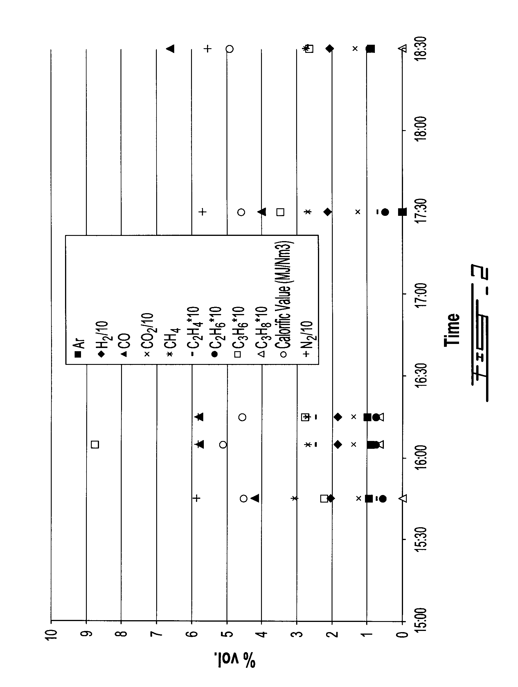
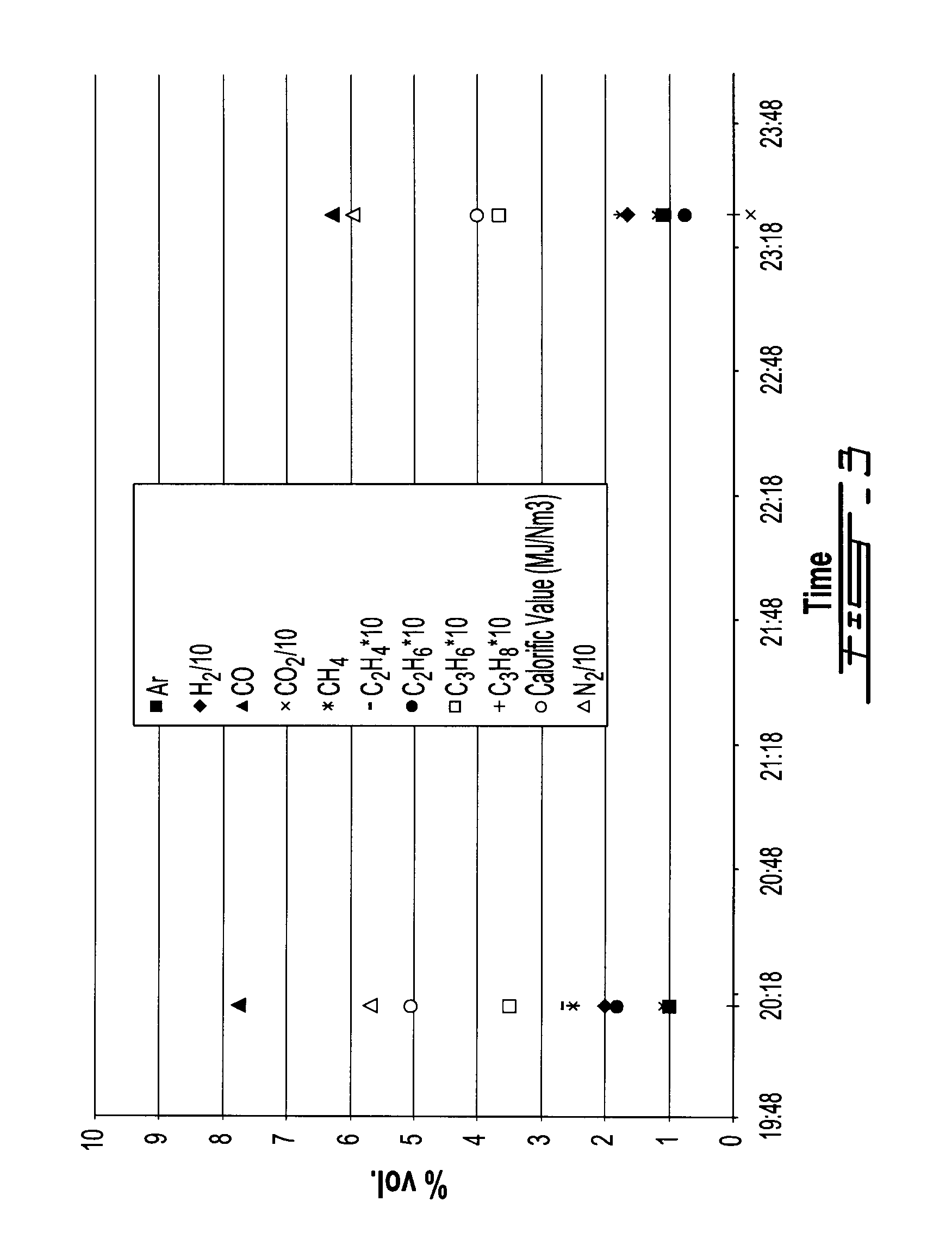
[0118]FIGS. 2 and 3, as well as Table 6 below, clearly show that a stable syngas composition is obtained throughout the 4 h tests. Table 6 gives the syngas average composition for each test.

TABLE 6TypesTest 1Test 2N257.857.8Ar0.81H21918.3CO5.97.7CO21312.3CH42.82.2C2H40.20.2C2H60.10.1C3H60.30.4C3H80.00.0CxHy0.00.0

Flue Gas Sampling

[0119]The flue gas sampling was conducted at the stack, following the...


PUM


Abstract

A method for co-producing a sulfur-containing raw synthetic gas and an essentially desulfurized solid residue from a sulfur-containing heavy petroleum residue feedstock, comprising feeding a bubbling fluidized-bed gasification reactor with the feedstock, and converting the feedstock to a raw synthetic gas by a partial oxidation reaction in the presence of water at a temperature at or below about 1000° C. and a pressure at or below about 10 atm, thereby also producing an essentially desulfurized solid residue, while the sulfur components are essentially comprised in the raw synthetic gas; and separately recovering the essentially desulfurized solid residue and the sulfur-containing raw synthetic gas.

Description

FIELD OF THE INVENTION[0001]The present invention relates to a method for low-severity gasification of heavy petroleum residues. More specifically, the present invention is concerned with the low-severity gasification of petroleum coke and asphaltenic-rich residues.BACKGROUND OF THE INVENTION[0002]The current production of heavy oil involves the use of large amounts of high-pressure steam injected in the geological zones where the heavy oil is embedded (for example in Steam-Assisted Gravity Drainage—SAGD). During the extraction process, the temperature in the steam-injection zone is increased, causing a reduction of the heavy oil viscosity. The heavy oil then drains towards a collector from which it is pumped to the surface, where it is recovered for in situ upgrading or transportation to an upgrader.[0003]Approximately, the enthalpy contained in 1 barrel (bbl) of oil needs to be consumed to produce the steam in order to lift 3 to 4 bbl of heavy oil. The cost of the heavy oil extrac...

Claims


Application Information

Patent Timeline
IPC IPC(8): C10J3/46
CPCC01B3/52C10K1/101C01B2203/0475C01B2203/0485C01B2203/0495C10J3/482C10J3/84C10J2300/0906C10J2300/0923C10J2300/094C10J2300/0943C10J2300/0956C10J2300/0983C10J2300/169C10J2300/1807C10J2300/1838C10L9/06Y02C20/20Y02E20/18C10J3/463C10K1/004C10K1/005C10K1/026C01B2203/0415
Inventor CHORNET, ESTEBANMINCIC, ACAGAGNON, MARTINVALSECCHI, BORIS
Owner ENERKEM INC
Learn More