
Pneumatic tire

a pneumatic tire and tyre technology, applied in the field of pneumatic tires, can solve the problems of air permeation prevention properties being lower, the elongation of the inner liner layer of the hook and loop fastener cannot follow the elongation of the inner liner layer,

Inactive Publication Date: 2010-01-28
YOKOHAMA RUBBER CO LTD
View PDF14 Cites 30 Cited by
  • Summary
  • Abstract
  • Description
  • Claims
  • Application Information

AI Technical Summary

Benefits of technology

[0007]An object of the present invention is to provide a pneumatic tire designed so that when a hook and loop fastener is fitted to the tire internal face of a pneumatic tire furnished with an inner liner layer consisting of a thermoplastic elastomer composition of a blend of thermoplastic resin and elastomer, or a thermoplastic resin, the hook and loop fastener can easily follow the elongation of the inner liner layer and is free from damaging of the inner liner layer.
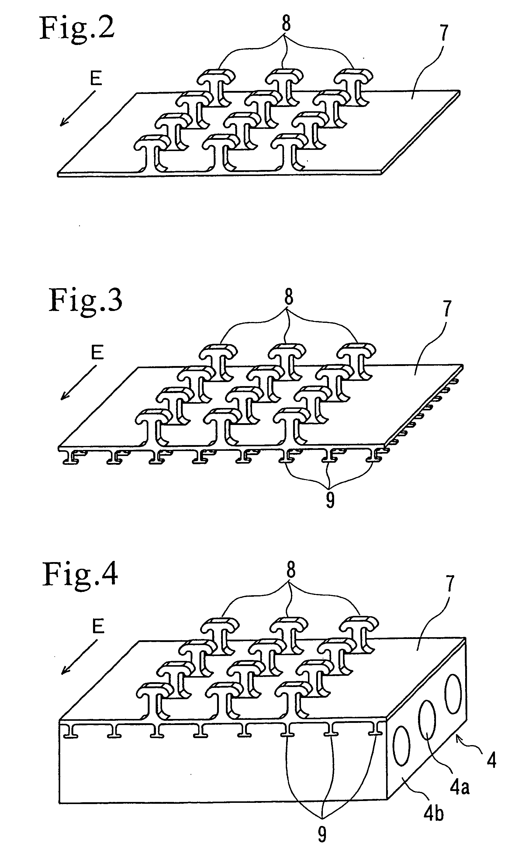
[0016]According to the present invention, in a pneumatic tire in which the inner liner layer is formed from a thermoplastic elastomer composition, or a thermoplastic resin, the interlocking elements of a hook and loop fastener are integrally molded with the inner liner layer, and therefore, it is possible to allow the interlocking elements to follow integrally to the elongation of the inner liner layer at the time of vulcanization molding and to leave the inner liner layer to be free from damage.

Problems solved by technology

However, for above-described tires fitted with an inner liner layer consisting of a thermoplastic elastomer composition containing thermoplastic resin as the main component, or a thermoplastic resin, there occurs a problem that, when fixing a hook and loop fastener to the inner liner layer using an adhesive or the like, the hook and loop fastener can not follow the elongation of the inner liner layer caused by expanding the diameter at the time of the vulcanization molding of the tire.
In addition, when providing a hook and loop fastener with an anchor element to be fixed penetratingly to the tire internal surface, there was such problem that air permeation-preventing properties lower because it damages the inner liner layer.Patent Document 1: Japanese patent application Kokai publication No. 8-258506Patent Document 2: Japanese patent application Kokai publication No. 2006-44503

Method used


Image

  • Pneumatic tire
  • Pneumatic tire
  • Pneumatic tire

Examples


Embodiment Construction

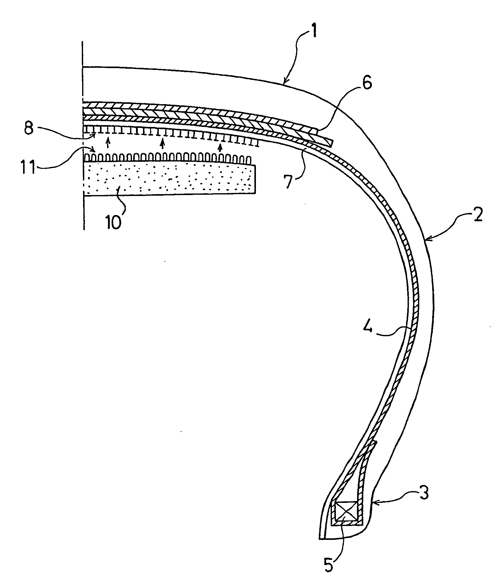
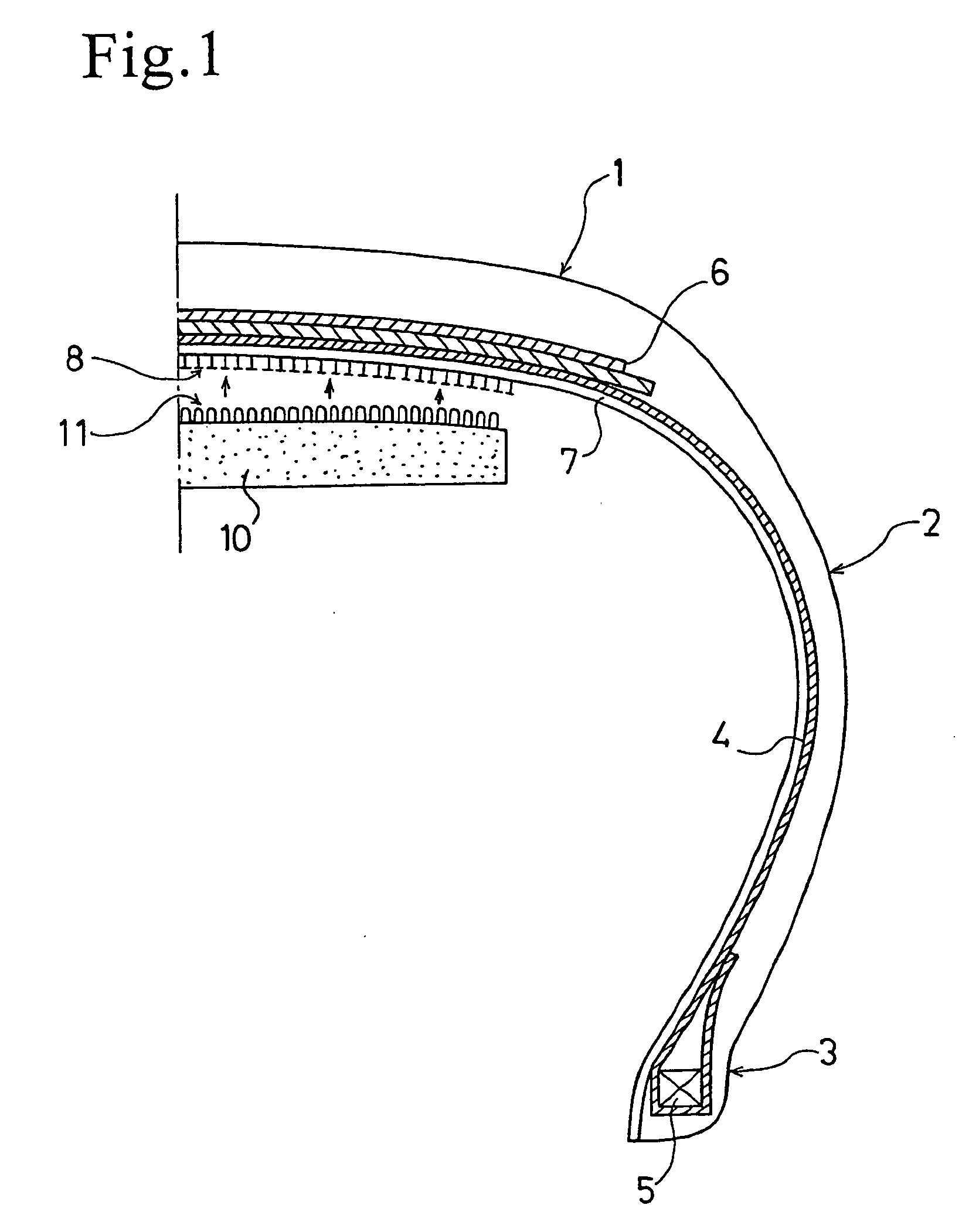
[0032]FIG. 1 is a half cross-sectional view in the tire meridional direction which shows one example of the embodiment of the pneumatic tire of the present invention.

[0033]In FIG. 1, 1 indicates a tread portion, 2 indicates a side wall portion, 3 indicates a bead portion, and 4 indicates a carcass layer. The carcass layer 4 is mounted between a pair of right and left bead cores 5 buried in the bead portion 3, and the both end portions thereof respectively are designed so as to be turned from the inside of the tire to the outside around bead core 5. Inside the tread portion 1, a pair of upper and lower belt layers 6 is arranged all the way around the tire outside the carcass layer 4. Further, on the innermost side of the tire, an inner liner layer 7 formed from a thermoplastic elastomer composition consisting of thermoplastic resin and elastomer, or a thermoplastic resin, is lined as the air permeation-preventing layer.

[0034]A multiplicity of interlocking elements 8 are integrally mo...


PUM


Abstract

A pneumatic tire designed so that when a hook and loop fastener is fitted to the tire internal face of a pneumatic tire furnished with an inner liner layer consisting of a thermoplastic elastomer composition of a blend of thermoplastic resin and elastomer, or a thermoplastic resin, the hook and loop fastener can easily follow the elongation of the inner liner layer and is free from damaging of the inner liner layer. There is disclosed a pneumatic tire furnished on its internal face with an inner liner layer (7) consisting of a thermoplastic elastomer composition composed of thermoplastic resin and elastomer, or a thermoplastic resin, characterized in that integral forming of a multiplicity of interlocking elements (8) protruding on the hollow side of the tire is effected on the surface of the inner layer (7).

Description

TECHNICAL FIELD[0001]The present invention relates to a pneumatic tire, and more specifically, to a pneumatic tire designed so that a hook and loop fastener for attaching such an accessory as an acoustic material is fitted to the tire internal face of a pneumatic tire furnished with an inner liner layer consisting of a thermoplastic elastomer composition of a blend of thermoplastic resin and elastomer, or a thermoplastic resin.BACKGROUND ART[0002]In a tubeless pneumatic tire, an inner liner layer consisting of butyl-based rubber having an excellent air-impermeable property is integrally lined to the tire internal face thereof as an air-permeation preventing layer. However, since the butyl-based rubber is heavy, Patent Document 1 proposes to use a thermoplastic resin having a small specific gravity or a thermoplastic elastomer composition containing the thermoplastic resin as a main component, in place of the butyl-based rubber.[0003]Meanwhile, recently, for the purpose of improving ...

Claims


Application Information

Patent Timeline
IPC IPC(8): B60C5/14
CPCB29D30/0061B29D2030/0072B60C19/002B60C23/0493B60C5/00B60C5/14B29D30/0681Y10T24/27Y10T24/2725Y10T24/2792Y10T428/24017Y10T152/10495
Inventor TANNO, ATSUSHISATO, YUJI
Owner YOKOHAMA RUBBER CO LTD
Learn More