
Sill Flashing

Inactive Publication Date: 2010-01-28
FLASHMAN FLASHING SYST LTD
View PDF16 Cites 5 Cited by
  • Summary
  • Abstract
  • Description
  • Claims
  • Application Information

AI Technical Summary

Benefits of technology

[0004]The sill flashing disclosed in New Zealand Patent No. 532728 disclosed a sill flashing which provided a reliable seal between the cladding and the bottom of the window frame, and also provided easy drainage for any water which penetrated past the flashing.
[0005]However, the flashing disclosed in New Zealand Patent No. 532728 was made in two pieces, which had to be fitted together to make the complete flashing. This increased both the production and the fitting cost, and also increased the risk of the fitting being incorrectly installed.
[0006]It is therefore an object of the invention to provide a sill flashing which, while retaining all of the advantages of the flashing of New Zealand Patent No. 532728, is formed as a single piece and thus is cheaper to make and install, and less liable to installation errors.

Problems solved by technology

This increased both the production and the fitting cost, and also increased the risk of the fitting being incorrectly installed.

Method used


Image

  • Sill Flashing
  • Sill Flashing
  • Sill Flashing

Examples


Embodiment Construction

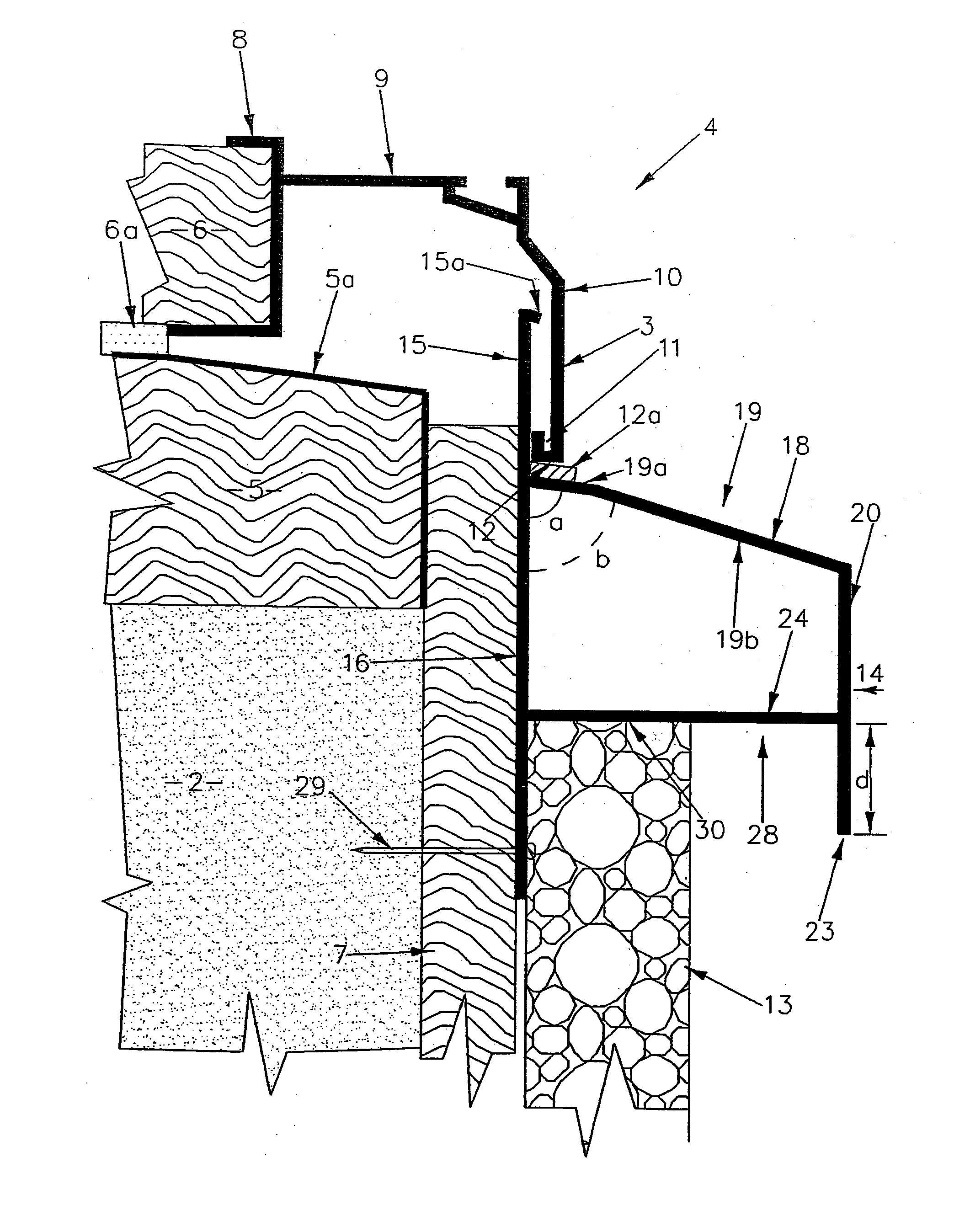
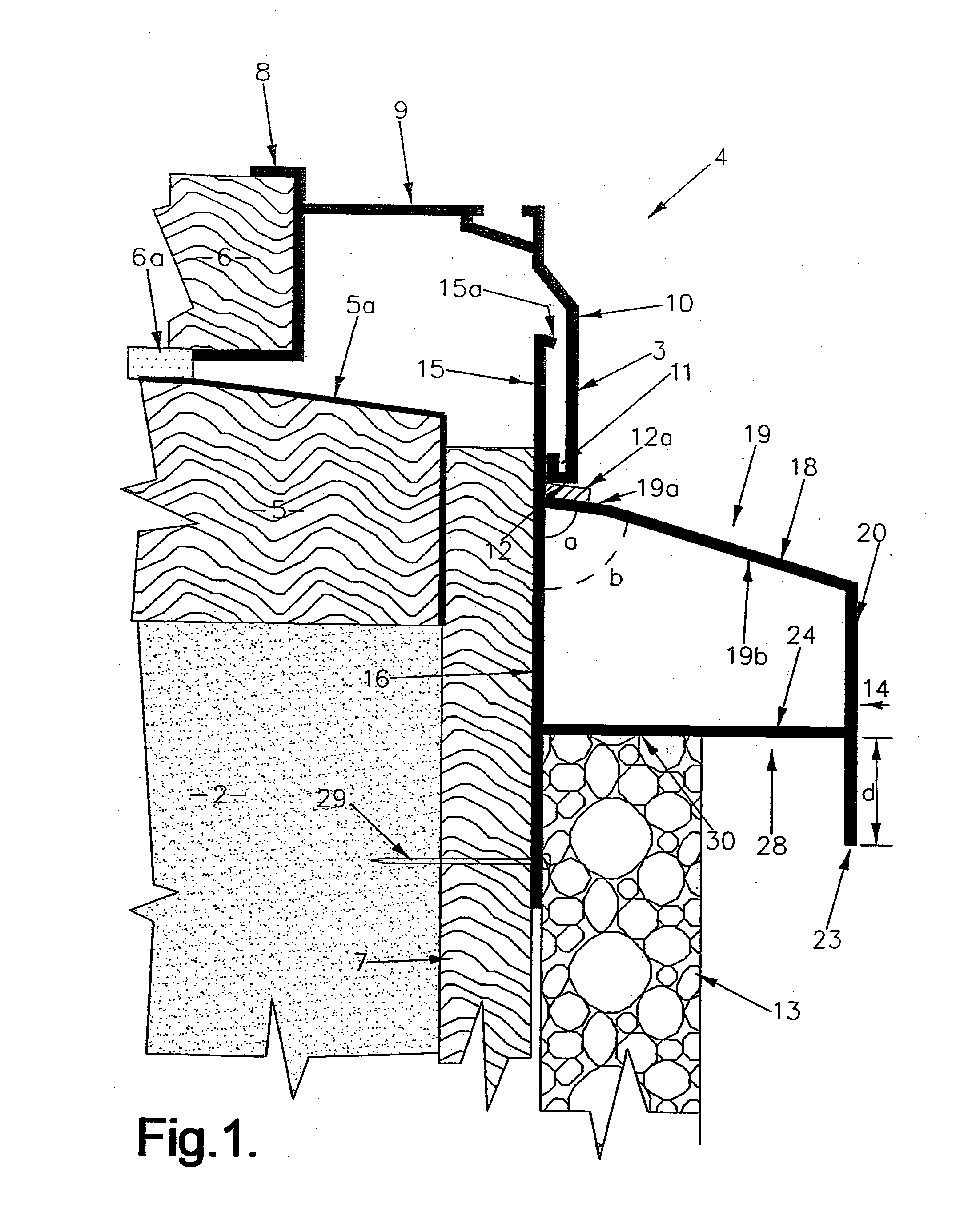
[0014]Referring to the drawings, the wall of a building adjacent the lower edge 3 of a window frame 4 consists of framing 2 supporting a horizontal sill trimmer 5, which supports an inner window reveal 6 and a series of spaced cavity battens 7. A packing strip 6a is located between the sill trimmer 5 and the reveal 6. The upper surface of the sill trimmer 5 is protected by a flexible waterproof wrap 5a of known type.

[0015]The window frame 4 is a known type and includes a channel portion 8 which fits over the inner window reveal, a portion 9 which provides seating for the glazing (not shown), and an outer portion 10 which forms the outer surface of the window frame. The lower edge of the portion 10 is in-turned to form a channel 11 with a substantially horizontal lower surface 12.

[0016]The cavity battens 7 are vertical strips of timber spaced apart in a horizontal plane and secured to the sill trimmer 5 and / or the framing 2. The purpose of the cavity battens is to provide a series of...


PUM


Abstract

A sill flashing adapted to be mounted below and parallel to the lower edge of a window frame, said sill flashing including: -a first portion adapted to lie behind the lower edge of a window frame; a second portion adapted to lie between the cladding and the framing beneath the lower edge of the window frame; a third portion designed to provide an outwardly inclined cover for the top edge of the cladding below the lower edge of the window frame; a fourth portion adapted to brace the lower edge of said third portion; wherein said first, second, third and fourth portions are formed integrally with each other.

Description

TECHNICAL FIELD[0001]The present invention relates to an improved sill flashing for use in combination with window frames, door frames, French window frames or sliding door frames. The flashing of the present invention has been developed specifically for use in combination with aluminium window frames, and therefore will be described with particular reference to this application. However, it should be appreciated that the flashing of the present invention is not restricted to this application, and in the specification the term “windows” includes doors, French windows, sliding doors and all similar components, and the frames may be made of any material, e.g. aluminium, plastics, wood.BACKGROUND ART[0002]A common method of building construction is to erect a building frame (typically of wood), cover the frame with a layer of building paper on the exterior of the building, and then apply cladding over the building paper. The cladding may be any of a wide variety of materials, e.g. plas...

Claims


Application Information

Patent Timeline
IPC IPC(8): E06B7/26
CPCE06B1/34E06B2001/628E06B1/702
Inventor HOTTON, STEPHEN JOHNANTICICH, MICHAEL
Owner FLASHMAN FLASHING SYST LTD
Learn More