Eureka AIR delivers breakthrough ideas for toughest innovation challenges, trusted by R&D personnel around the world.

Electric heating pipe head multifunctional protecting connector and electric heating pipe head sealing method

An electric heating tube, multi-functional technology, applied in the sealing of the engine, the shape of the heating element, the engine components, etc., can solve the problems of overcurrent damage of the electric heating tube, material leakage, rupture of the electric heating tube shell, etc., and achieve reliable sealing, Guarantees insulation performance and prevents leakage

Active Publication Date: 2014-09-24
ZHENJIANG DONGFANG ELECTRIC HEATER +1
View PDF5 Cites 4 Cited by
  • Summary
  • Abstract
  • Description
  • Claims
  • Application Information

AI Technical Summary

Problems solved by technology

The existing installation method of the electric heating tube has the following defects: 1. In actual use, the shell of the electric heating tube located in the container may rupture due to overheating, and the heated medium may enter the shell of the electric heating tube, and then pass through the shell of the electric heating tube. The thermally conductive and insulating medium (such as magnesium oxide powder) in the casing seeps out from the end of the electric heating tube, resulting in material leakage; 2. For some high-power industrial electric heaters, a large number of electric heating tubes are usually used to work at the same time. The overcurrent protection of electric heaters usually only monitors the overall current of all electric heating tubes, so when a single electric heating tube is overcurrent, it is difficult for the overcurrent protection system to detect and protect it in time, resulting in overcurrent damage to the electric heating tube

Method used


Image

  • Electric heating pipe head multifunctional protecting connector and electric heating pipe head sealing method

Examples


Embodiment Construction

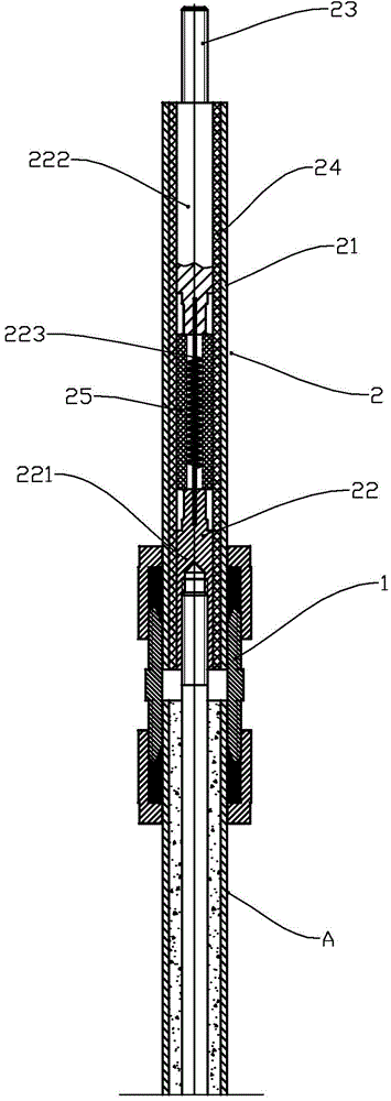
[0013] As shown in the figure, the embodiment of the electric heating tube multifunctional protective connector of the present invention includes a pipe joint 1 and a sealing tube assembly 2; the sealing tube assembly includes a section of a metal outer tube 21 and a central conductor 22 located at the center of the metal outer tube, One end of the central conductor has a structure that can be matched and connected with the lead-out conductor of the electric heating tube, and the other end of the central conductor has a lead-out rod 23 that can be connected to an external power source; the central conductor 22 and the metal outer tube 21 are sealed by polytetrafluoroethylene material The sleeve 24 is sealed and filled; the pipe joint 1 (a known bite-type pipe joint can be used) can seal the metal outer pipe 21 and the tubular shell of the electric heating pipe 3. The central conductor 22 is composed of a front conductive bar 221 located in the front section, a rear conductive ba...


PUM


Abstract

The invention relates to a part structure of an electric heating device, in particular to an electric heating pipe head multifunctional protecting connector which comprises a pipe connector and a sealing pipe component. The sealing pipe component comprises a section of metal outer pipe and a center conductor placed at the center of the metal outer pipe. One end of the center conductor is provided with a structure which can be connected with an electric heating pipe guiding-out end conductor in a matched mode. The other end of the center conductor is provided with a guiding-out rod which can be connected with an external power supply. The position between the center conductor and the metal outer pipe is provided with a sealing sleeve made of polytetrafluoroethylene material for sealing and filling. The metal outer pipe and a tubular outer shell of an electric heating pipe can be connected in a sealing mode through the pipe connector. Dielectric can be effectively prevented from leaking from an electric heating pipe inner core, a single electric heating pipe can be subjected to overcurrent protection, external moisture can be effectively prevented from entering the electric heating pipe inner core, and the insulating property of insulated dielectric is guaranteed.

Description

Technical field [0001] The invention relates to a component structure of an electric heating device, in particular to a multifunctional protective connector for an electric heating tube head and a sealing method for the electric heating tube head. Background technique [0002] In an electric heater using an electric heating tube, the end of the electric heating tube is usually connected to the power terminal in the junction box through a lead-out rod. The tubular shell of the electric heating tube is usually sealed with the window wall plate to ensure that the container is heated The medium will not leak. The existing installation method of the electric heating tube has the following defects: 1. In actual use, part of the electric heating tube shell located in the container may be broken due to overheating, and the heated medium may enter the electric heating tube shell and pass through The heat-conducting insulating medium (such as magnesium oxide powder) in the shell seeps fro...

Claims


Application Information

Patent Timeline
IPC IPC(8): H05B3/40F16J15/06
Inventor 谭克
Owner ZHENJIANG DONGFANG ELECTRIC HEATER
Why Eureka
Eureka Blog
Learn More