Navigation system and lane information display method

a navigation system and information display technology, applied in navigation instruments, maps/plans/charts, instruments, etc., can solve the problems of discrepancy between directions and difficulty in clearly determining the direction of each lane at the branch poin

Active Publication Date: 2010-01-21
AUTO TECH GRP LLC
View PDF23 Cites 14 Cited by
  • Summary
  • Abstract
  • Description
  • Claims
  • Application Information

AI Technical Summary

Benefits of technology

[0008]Because the navigation system in accordance with the present invention is constructed in such a way as to determine the direction of each of the lanes on the basis of both the lane information and the road attribute of the incoming road coming into the intersection and the road attributes of the outgoing roads extending from the intersection, the road attributes of the incoming and outgoing roads being included in the map data, and then display the direction of each of the lanes which it has determined through the lane direction determination with an arrow, it can prevent the user from having any illusion and can display a lane guide map which meets users' feeling.

Problems solved by technology

A problem is however that in the lane guide map displayed by the above-mentioned conventional navigation system, a discrepancy may occur between the direction of each lane displayed on this lane guide map with an arrow and the direction of each lane which the driver recognizes.
Furthermore, because the angle between an incoming road coming into a branch point on a highway and an outgoing road extending from the branch point is small in many cases, it is difficult to clearly determine the direction of each lane at the branch point, such as a straightforward direction, a diagonal right direction, or a diagonal left direction, from this angle.
Therefore, a problem is that the directions of all lanes at an intersection for guidance may be expressed as straightforward arrows in the lane guide map displayed by the conventional navigation system.

Method used


Image

  • Navigation system and lane information display method
  • Navigation system and lane information display method
  • Navigation system and lane information display method

Examples


embodiment 1

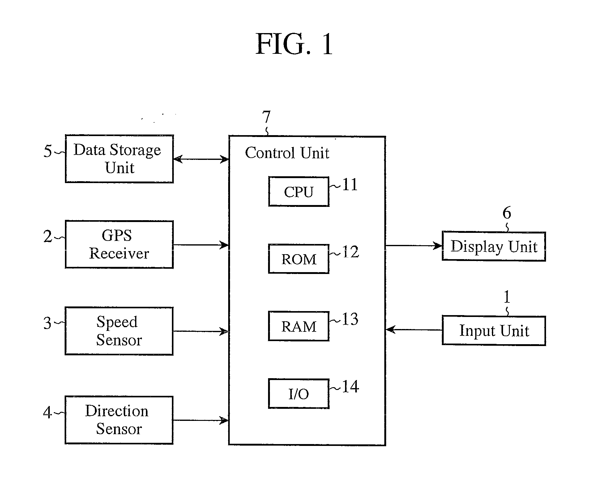
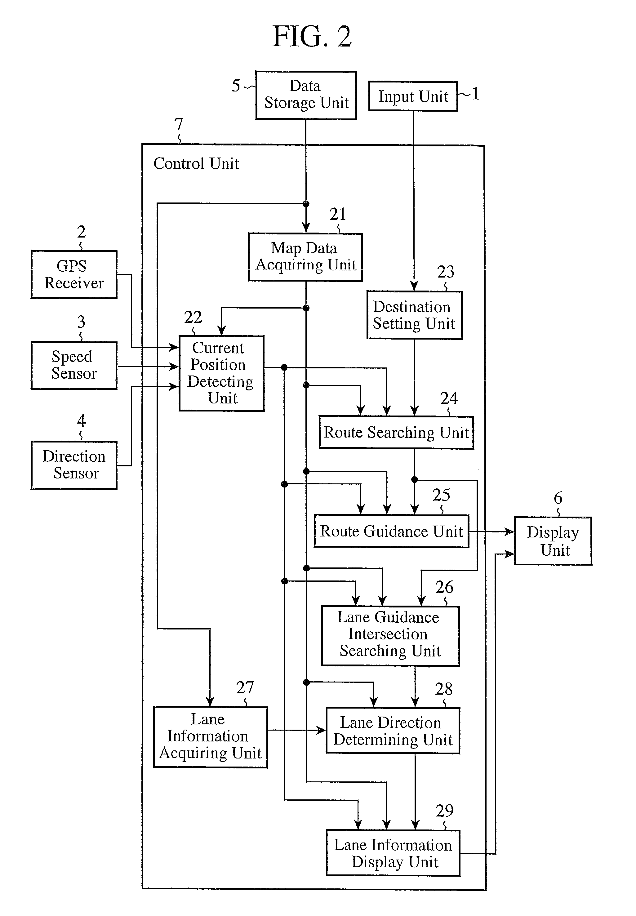
[0030]FIG. 1 is a block diagram showing the hardware configuration of a navigation system in accordance with Embodiment 1 of the present invention. This navigation system is provided with an input unit 1, a GPS (Global Positioning System) receiver 2, a speed sensor 3, a direction sensor 4, a data storage unit 5, a display unit 6, and a control unit 7.

[0031]The input unit 1 is comprised of, for example, a touch panel placed on the screen of the display unit 6. This input unit 1 is used in order for a user to, for example, set up a place of departure, a destination, or a via-place for route search, and to provide various instructions to the navigation system. Either data showing the place of departure, the destination, or the via-place inputted from this input unit 1 or a signal showing an instruction inputted from the input unit 1 is sent to the control unit 7.

[0032]The GPS receiver 2 detects the current position of a vehicle on the basis of GPS signals received from GPS satellites. ...

embodiment 2

[0069]A navigation system in accordance with Embodiment 2 of the present invention is constructed in such a way as to determine the direction of each lane from the road class of each road which forms an intersection. Because the structure of the navigation system in accordance with this Embodiment 2 is the same as that of the navigation system in accordance with above-mentioned Embodiment 1, the explanation of the structure will be omitted hereafter.

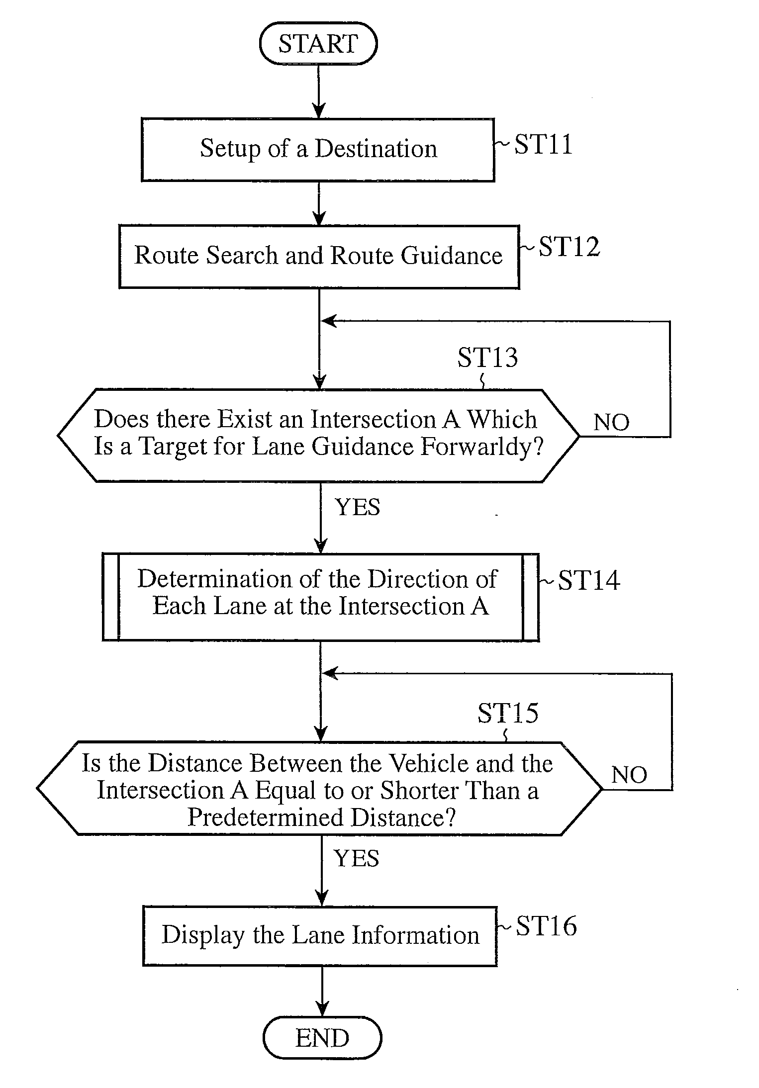
[0070]Next, the operation of the navigation system in accordance with Embodiment 2 of the present invention will be explained. Because the operation of this navigation system differs from that of the navigation system in accordance with Embodiment 1 in only the direction determining process of determining the direction of each lane performed in step ST14 of the lane information display process shown in the flow chart of FIG. 3, only a different portion will be explained hereafter.

[0071]FIG. 8 is a flowchart showing the details of the dir...

embodiment 3

[0082]A navigation system in accordance with Embodiment 3 of the present invention is constructed in such a way as to determine the direction of each lane from a road name or a road number (simply referred to as a “road name” from here on) of each road which forms an intersection. Because the structure of the navigation system in accordance with this Embodiment 3 is the same as that of the navigation system in accordance with above-mentioned Embodiment 1, the explanation of the structure will be omitted hereafter.

[0083]Next, the operation of the navigation system in accordance with Embodiment 3 of the present invention will be explained. Because the operation of this navigation system differs from that of the navigation system in accordance with Embodiment 1 in only the direction determining process of determining the direction of each lane performed in step ST14 of the lane information display process shown in the flow chart of FIG. 3, only a different portion will be explained her...


PUM


Abstract

A navigation system includes a lane information acquiring unit 27 for acquiring both the number of lanes of a road which forms an intersection, and lane information which defines a road branching off from each of the lanes, a lane direction determining unit 28 for determining the direction of each of the lanes on the basis of both the lane information acquired by the lane information acquiring unit, and a road attribute of an incoming road coming into the intersection and a road attribute of an outgoing road extending from the intersection, the road attributes of the incoming and outgoing roads being included in map data acquired by a map data acquiring unit, and a lane information display unit 29 for displaying the direction of each of the lanes determined by the lane direction determining unit with an arrow.

Description

FIELD OF THE INVENTION[0001]The present invention relates to a navigation system for and a lane information display method of guiding a user to his or her destination. More particularly, it relates to a technology of displaying the direction of each lane at an intersection on a guidance screen.BACKGROUND OF THE INVENTION[0002]Conventionally, a navigation system that displays a lane guide map showing the direction of each lane formed on a road with an arrow is known. This conventional navigation system determines the direction of each lane which is to be displayed on such a lane guide map with an arrow on the basis of the actual geometry of roads. Therefore, for example, in a case of an intersection in which a main road curves rightwardly and a bypass branching off from the main road extends in a straightforward direction, a lane guide map in which the bypass is shown by a straightforward arrow and the main road is shown by an arrow bent toward a diagonal right direction is displayed...

Claims


Application Information

Patent Timeline
IPC IPC(8): G01C21/26
CPCG09B29/10G01C21/3658
Inventor IRIE, TAKASHIKOMATSU, NAOMIKIAKASHI, YOSHIKINISHIBASHI, KUMI
Owner AUTO TECH GRP LLC
Why Eureka
Try Eureka