
Device for vertebral stabilization

a technology for fixing devices and vertebrae, which is applied in the field of vertebral stabilization devices, can solve the problems of limiting the thickness of the anchor body, the size of any vertebral fixing device, and the size of any fixing devi

Inactive Publication Date: 2010-01-14
PARK GI HOON
View PDF9 Cites 86 Cited by
  • Summary
  • Abstract
  • Description
  • Claims
  • Application Information

AI Technical Summary

Benefits of technology

[0014]Accordingly, the present invention has been made to solve the above-mentioned problems occurring in the prior art. A vertebral fixing device of the present invention adapted a constrainer and pivot to freely swivel with regard to the anchor so that it can be easily coupled to a connecting rod, which has no limitation on the diameter of the anchor body.
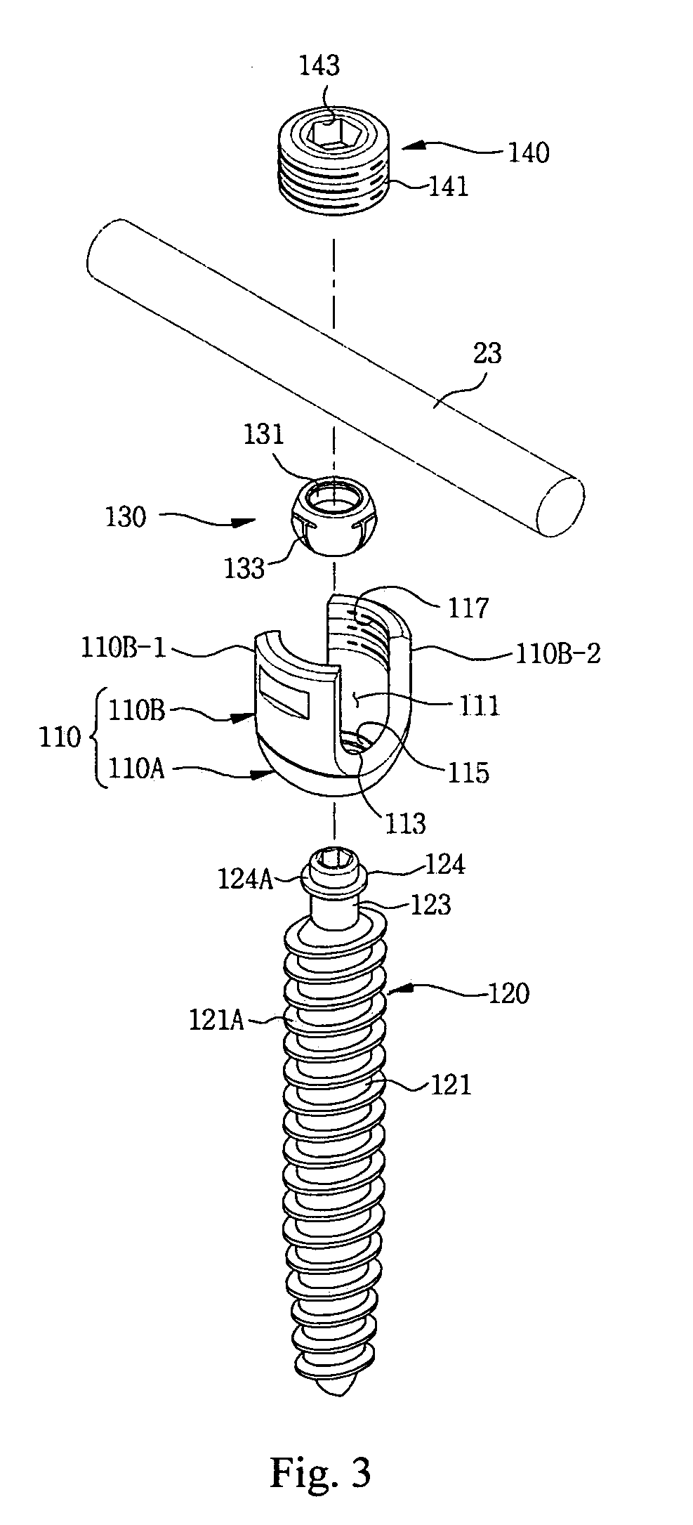
[0017]An annular ring (124) of the anchor is snapped to fit into the snap-fitting groove (135) of the pivot, when the stem of the anchor is aligned to the inserting hole of the pivot and depressed, so that the annular ring of the anchor is snapped into fit the snap-fitting groove The annular ring (124) has a lateral surface (124A), which is gradually widened to have a slanted lateral surface, so that the snap-fitting annular ring (124) can be easily and firmly inserted into the insertion hole (131) of the pivot (130).

Problems solved by technology

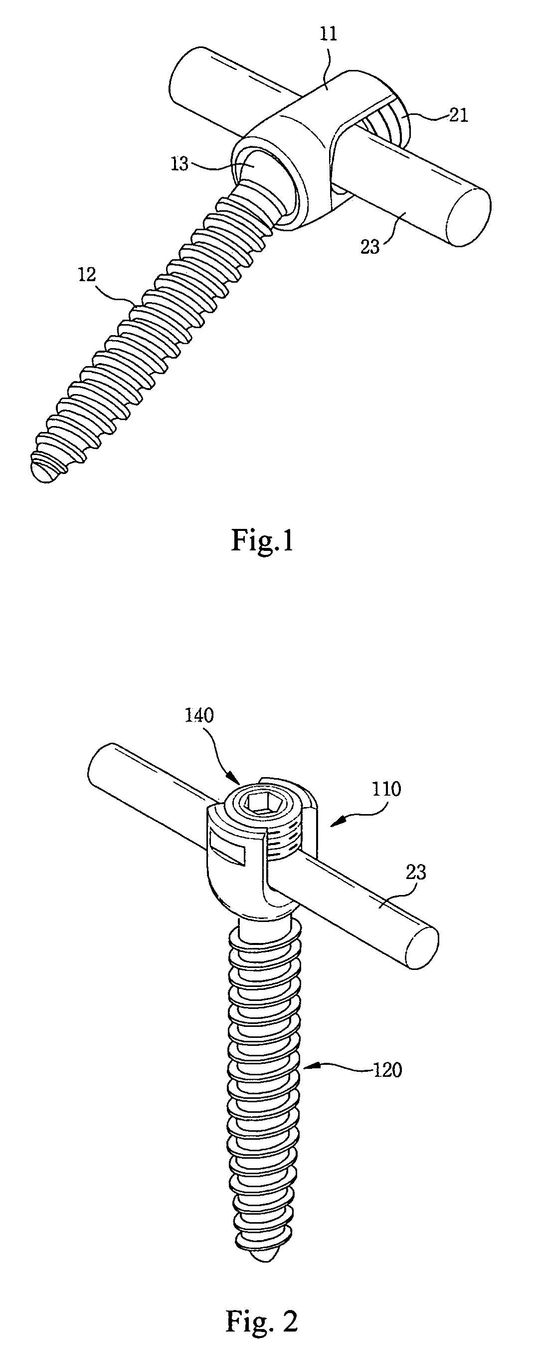
However, the conventional vertebral fixing device has a serious problem resulting from the structural requirement that the rotatable ball-type anchor head 13 must engage with the constrainer 11 while the anchor body 12 must pass through the constrainer 11.
As widely known in the art, the size of any vertebral fixing device is limited to a great extent because it is a small device intended to be installed into the human body along with other devices, including a connecting rod 23 and a crosslink for interconnecting a pair of connection rods.
However, the fact that the anchor head 13 must engage with the constrainer 11 while the anchor body 12 must pass through the constrainer 11 in the case of the conventional vertebral fixing device inevitably limits the thickness of the anchor body 12.

Method used


Image

  • Device for vertebral stabilization
  • Device for vertebral stabilization
  • Device for vertebral stabilization

Examples


Embodiment Construction

[0029]Hereinafter, an exemplary embodiment of the present invention will be described with reference to the accompanying drawings. The identifying or similar components are used the same reference numerals in the following description and drawings. Thus, the repetition of the descriptions for the same or similar components will be avoided.

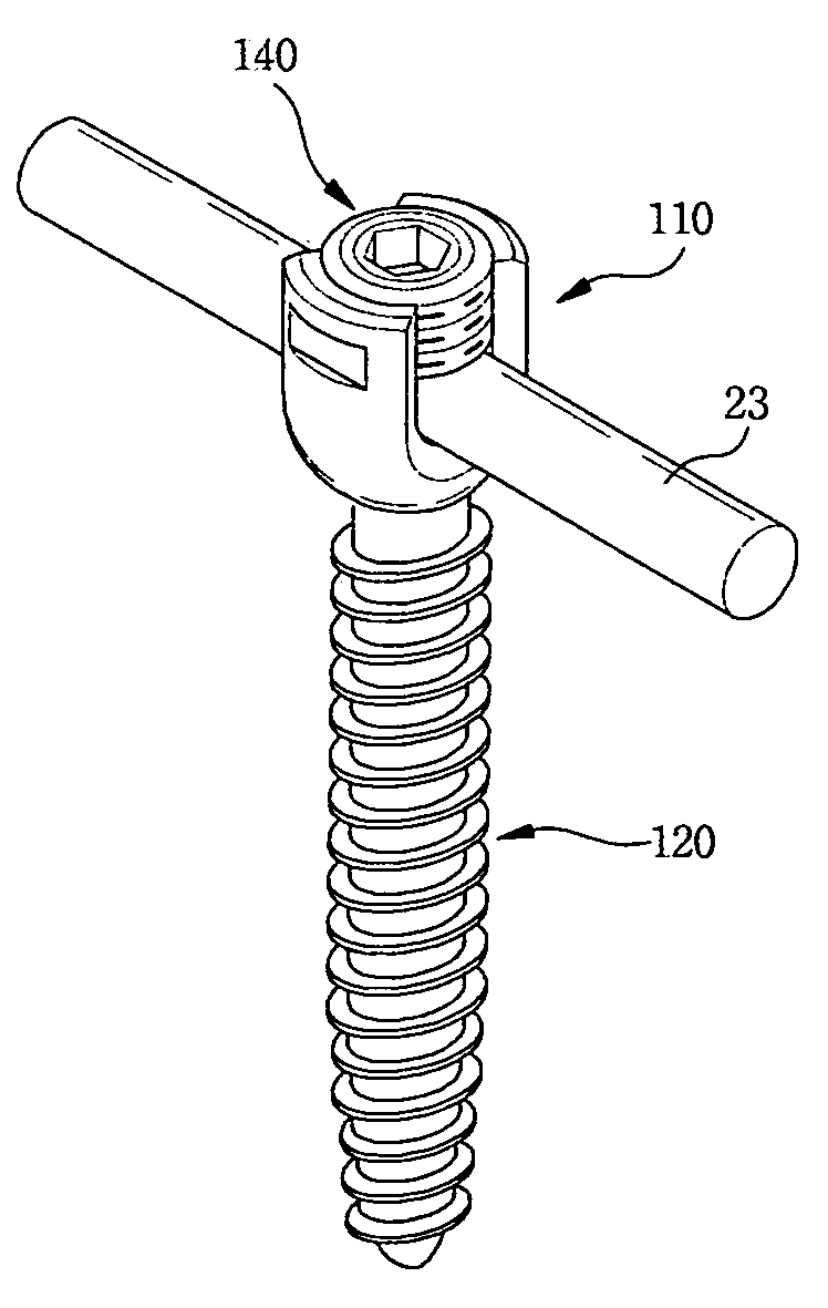
[0030]FIG. 2 is a perspective view of a vertebral fixing device according to the present invention. Although the vertebral fixing device of the present invention shown in FIG. 2 looks quite similar to the conventional vertebral fixing device, which has an anchor head thicker than the body so that the head engages with the constrainer while the body passes through the constrainer, a device of the instant invention is substantially different as follows: the stem of the anchor 120 is small enough to be passed through a pivot 130, and inserted into a constrainer nut 140. The pivot 130 and the constrainer nut 140, which are separated members, are couple...


PUM


Abstract

A device for fixing vertebral has developed that is comprising: a constrainer having a constraint base and a constraint mount forming two lateral cutouts for receiving a connecting rod; an anchor having a screw for installing into the vertebral, a stem to be inserted into the constrainer, and an annular ring; a pivot having an insertion hole, a plurality of slits extended from a mouth of insertion hole, a snap-fitting groove forming on the inner peripheral surface for snapping-fit to the annular ring: and a constraint nut having a male thread formed on outer peripheral surface, and a hexagonal recess on the head for rotating by a tool. When the constraint nut is rotated clockwise, the constraint members and connecting rod are depressed against the peripheral seat to be immobile. But, the counterclockwise rotation of constraint nut makes the constraint members releasing and the pivot is free to swivel with respect to the anchor.

Description

BACKGROUND OF THE INVENTION [0001]1. Field of the Invention[0002]The present invention relates to a vertebral fixing device, and more particularly, the vertebral stabilizer has adapted a pivot to freely swivel with respect to the anchor and a constrainer to fix at a proper location, so that it can be easily positioned, adjusted and tightly coupled to a connecting rod. The free swiveling of the pivot and constrainer can solve the problem of the limited anchor diameter for installing into a vertebra, and avoid the problem of the bulky head of anchor.[0003]2. Description of the Prior Art[0004]As generally known in the surgical technology, the degenerative vertebral diseases including the disk degenerative diseases (DDD), spinal stenosis and spondylolisthesis are subjected to conservative treatment first, and if no improvement occurs, surgical treatment follows. The surgical treatment consists of decompression, fusion (ALIF, PLIF, or posterolateral fusion), and fixation for fixing verte...

Claims


Application Information

Patent Timeline
IPC IPC(8): A61B17/70A61B17/04
CPCA61B17/7037
Inventor PARK, GI-HOON
Owner PARK GI HOON
Learn More