
Network interference evaluating method, dynamic channel assignment method and apparatus used in wireless networks

a dynamic channel assignment and wireless network technology, applied in the field of wireless network, can solve the problems of poor address of direct impact on interference performance, loss of interference prediction accuracy in some scenarios, etc., and achieve the effect of simple software upgrades

Inactive Publication Date: 2010-01-14
NEC (CHINA) CO LTD
View PDF19 Cites 30 Cited by
  • Summary
  • Abstract
  • Description
  • Claims
  • Application Information

AI Technical Summary

Benefits of technology

[0060]The positive effects of the invention are listed as follows:[0061]1. The interference degree prediction is driven by actual measurements thereby avoiding simplifying assumptions about the nature of wireless signal propagation.[0062]2. It can more accurately imply the network performance running under different settings.[0063]3. The invention does not require changes at the MAC layer and can be implemented through simple software upgrades. The proposals are back compatible with existing network standard such as 802.11.
[0061]1. The interference degree prediction is driven by actual measurements thereby avoiding simplifying assumptions about the nature of wireless signal propagation.
[0062]2. It can more accurately imply the network performance running under different settings.
[0063]3. The invention does not require changes at the MAC layer and can be implemented through simple software upgrades. The proposals are back compatible with existing network standard such as 802.11.

Problems solved by technology

However, other factors directly impacting the performance of interference are not well addressed in the proposed methods, they are:1. The signal power between the sender and the receiver (hereunder it is referred to as “good signal”)2. The traffic amount of the receiver.3. SINR rate table
Without the information, interference prediction loses accuracy in some scenarios.
For example:1. For two receivers A and B, when the strengths of their interfering signals are the same, but the receiver A is closer to its sender than the receiver B. In practice, the packet loss of the receiver A is much less than the receiver B, which means the interference degree the receiver A suffering is less than that of the receiver B. However, the existing methods fail to imply the situation, because it is not relevant with good signal.2. Even if the receiver B is suffering from strong interfering signal, there is no actual interference impact to the receiver B if the receiver B has no traffic to communicate at this time.

Method used


Image

  • Network interference evaluating method, dynamic channel assignment method and apparatus used in wireless networks
  • Network interference evaluating method, dynamic channel assignment method and apparatus used in wireless networks
  • Network interference evaluating method, dynamic channel assignment method and apparatus used in wireless networks

Examples


Embodiment Construction

[0071]Hereunder, the present invention will be described in accordance with the drawings. In the following description, some particular embodiments are used for the purpose of description only, which shall not be understood as any limitation to the present invention but the examples thereof. While it may blur the understanding of the present invention, the conventional structure or construction will be omitted.

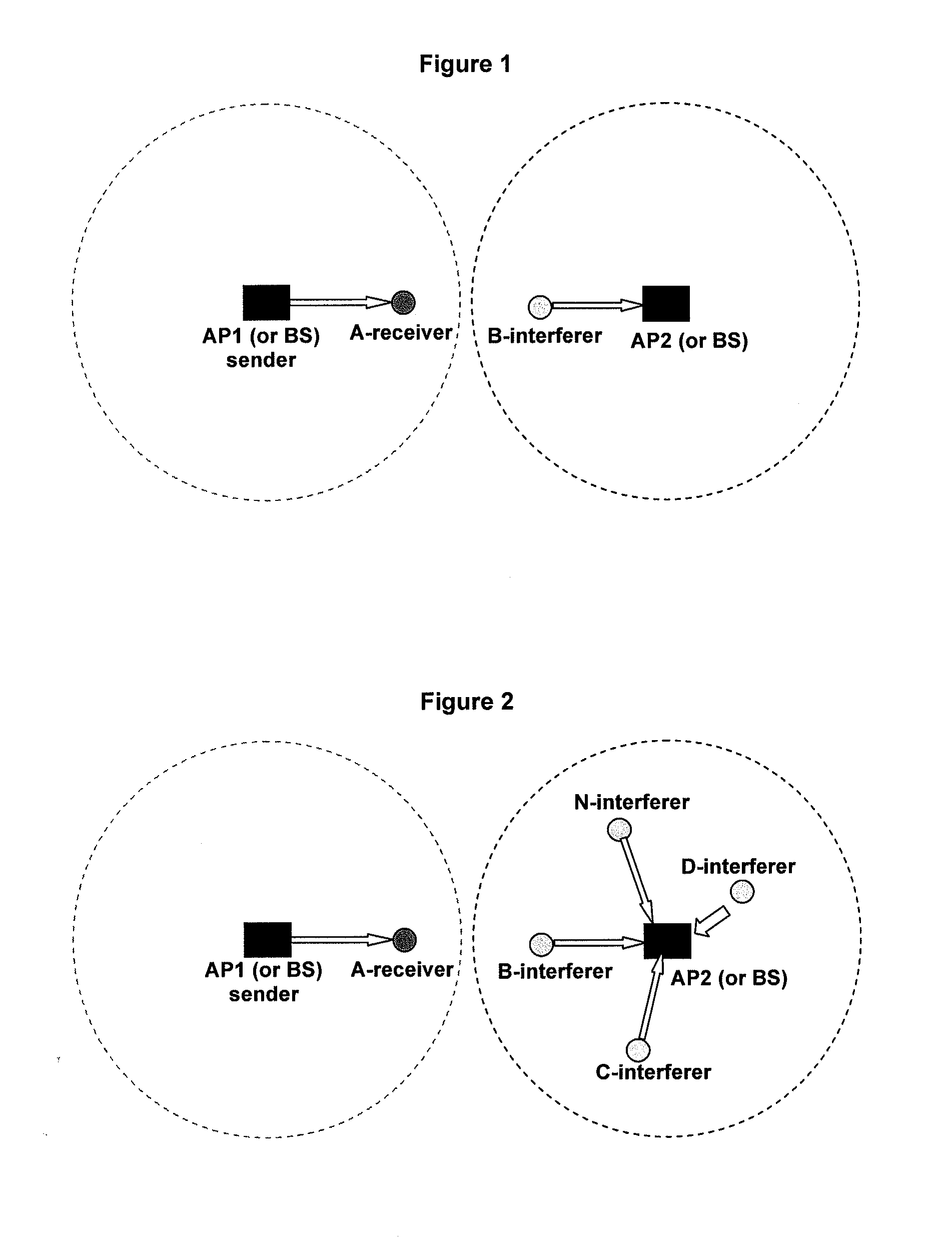
[0072]A simple case for the invention applied is shown in FIG. 1. In the cell of AP1, AP1 is transmitting traffic to a node A. In the cell of AP2, a node B is simultaneously transmitting traffic to AP2. When the two cells use the same channel, the node B is an interferer to the receiver—the node A.

[0073]To evaluate the interference degree from the node B to the node A, the parameters the node A needs to collect are listed in Table 2.

TABLE 2parameters to be collected by the receiverParameterExplanationRatexWithout interfernce, normal transsmion rate of node xx ∈ Set of Access P...


PUM


Abstract

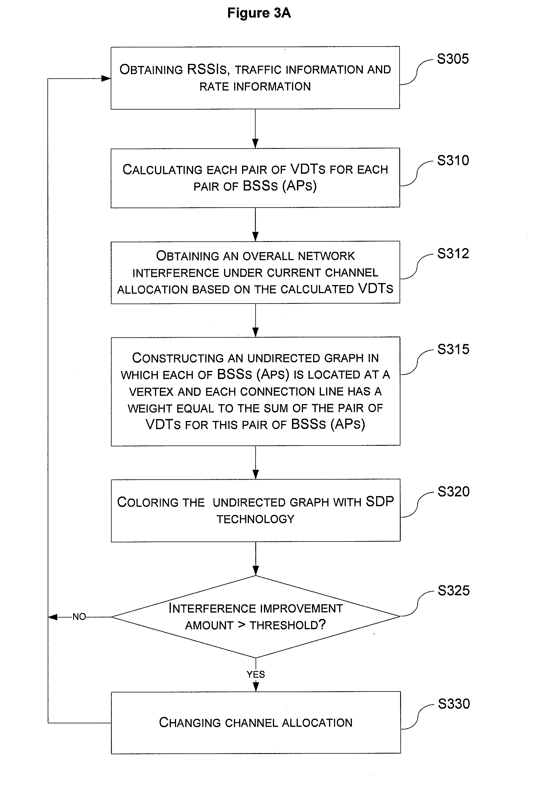
There are disclosed a network interference evaluating method, a dynamic channel assignment method and apparatus used in wireless networks. The dynamic channel assignment method used in a wireless network, comprising steps of: calculating each pair of visual delayed time for each pair of basic service sets based on received signal strength indicators, traffic information and rate information, and evaluating an overall network interference under a current channel allocation based on the calculated visual delayed time; constructing an undirected graph so that each basic service set is located at a vertex, and each connection line between each pair of basic service sets has a weight obtained from the pair of visual delayed time for this pair of basic service sets; coloring the undirected graph to get a new channel allocation approach and an optimized minimal overall network interference under this new channel allocation approach; comparing a difference between the evaluated overall network interference under the current channel allocation and the optimized minimal overall network interference with a predetermined threshold; and changing channel allocation for the basic service sets according to the new channel allocation approach if the difference is larger than the predetermined threshold.

Description

BACKGROUND OF THE INVENTION[0001]1. Field of Invention[0002]This invention relates to wireless network such as 802.11 WLANs, and more particularly, to a network interference evaluating method, a dynamic channel assignment method and apparatus used in the wireless network.[0003]2. Description of Prior Art[0004]Wireless networks such as 802.11 WLANs have enjoyed an unprecedented adoption rate in recent years. Generally, the network contains several cells and each cell includes one base station (BS) and many mobile stations (STAs) associated with it. The communications of the STAs must be relayed by the BS. In the context, we use 802.11 WLAN as an example to discuss the issue details, but it shall be noted that the present invention is not intended to be limited in the 802.11 WLAN scenario. In the 802.11 WLANs, the cell is called BSS (Basic Service Set), the BS is called Access Point (AP) and channel refers to wireless frequency spectrum allotted to the WLAN. The 802.11 specification d...

Claims


Application Information

Patent Timeline
IPC IPC(8): H04W72/00H04J1/16
CPCH04W72/082H04W72/541
Inventor LIU, YONGQIANGLUO, YANLINCHEN, SONGJIEWANG, GANG
Owner NEC (CHINA) CO LTD
Learn More