Eureka AIR delivers breakthrough ideas for toughest innovation challenges, trusted by R&D personnel around the world.

Portable x-ray detector with grid sensing unit and x-ray imaging system for automatic exposure setting for the portable x-ray detector

a x-ray detector and automatic exposure technology, applied in the field of xray imaging, can solve the problems of deteriorating the signal-to-noise ratio too much, and achieve the effect of high-quality x-ray imag

Inactive Publication Date: 2010-01-07
KONINKLIJKE PHILIPS ELECTRONICS NV
View PDF6 Cites 28 Cited by
  • Summary
  • Abstract
  • Description
  • Claims
  • Application Information

AI Technical Summary

Benefits of technology

[0015]This first aspect of the invention is based on the idea that an automatic sensing of the presence of an optional anti scatter grid provides a reliable and useful information for a radiographer in order to adapt proper default exposure settings of an X-ray source in the moment an anti scatter grid is attached. Therefore, the risk of over- or under-exposures of X-ray images may be reduced. In particular, the risk to apply a too high radiation dose to a patient in case that an anti scatter grid is erroneously not used can be minimized effectively. Therefore, the workflow of acquiring X-ray images is simplified such that also a less experienced user can operate an X-ray imaging system comprising the described portable detector.
[0043]According to an embodiment of the invention the step of operating an X-ray source is further based on an output signal of an automatic exposure control unit, which is associated with X-ray detector unit. As has already been described above such an online monitoring of the radiation dose may provide the advantage that the X-ray exposure of an object under examination may be immediately stopped if a sufficient radiation dose has been received by the X-ray detector unit in order to allow a high quality X-ray image without having the risk of an over-exposure of a patient under examination.

Problems solved by technology

For thin objects an anti scatter grid is typically not used because compared to the effect of a contrast enhancement the effect of deteriorating the signal to noise ratio is too big.

Method used


Image

  • Portable x-ray detector with grid sensing unit and x-ray imaging system for automatic exposure setting for the portable x-ray detector
  • Portable x-ray detector with grid sensing unit and x-ray imaging system for automatic exposure setting for the portable x-ray detector
  • Portable x-ray detector with grid sensing unit and x-ray imaging system for automatic exposure setting for the portable x-ray detector

Examples


Embodiment Construction

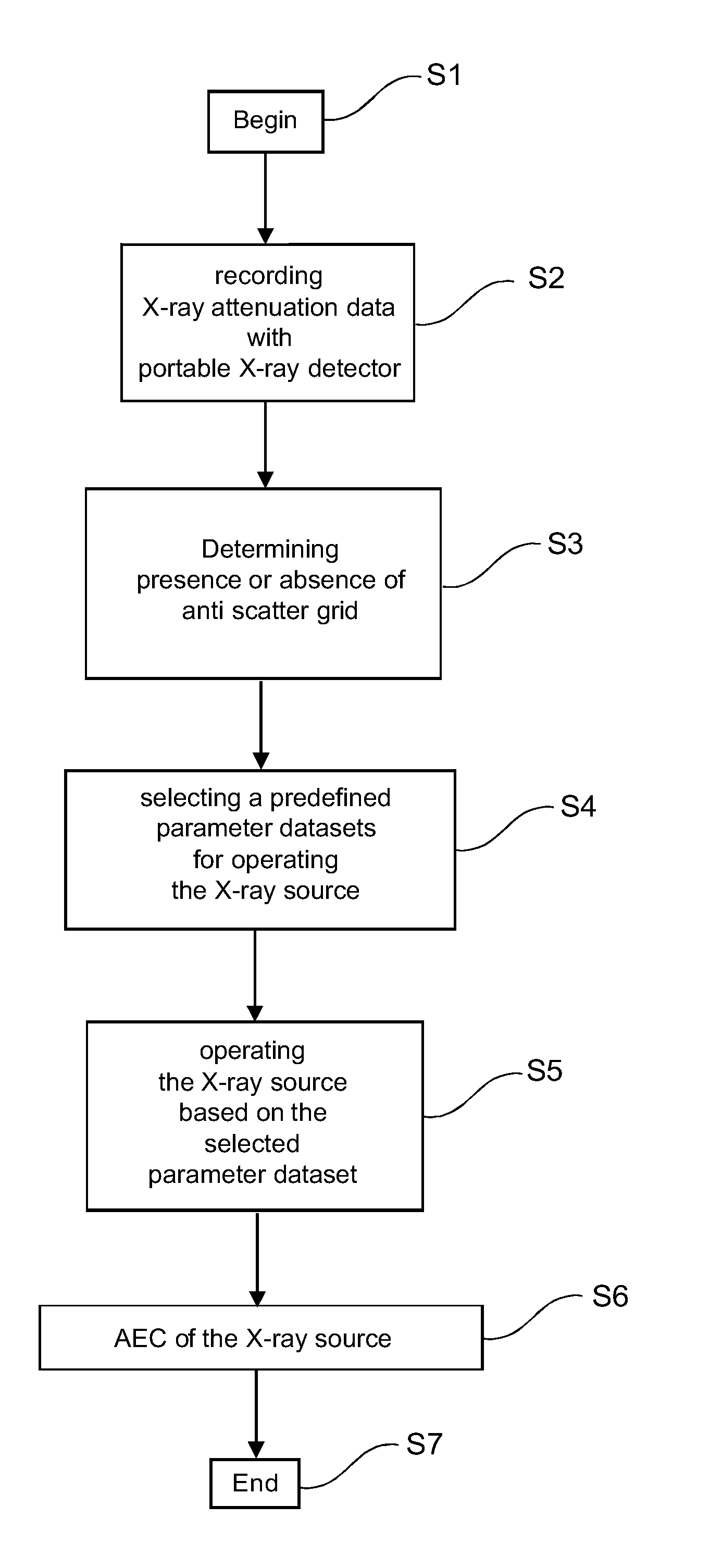
[0052]FIG. 1 shows a flow chart how a method for acquiring X-ray image data with a portable X-ray detector may be carried out. The method starts with a step S1.

[0053]In step S2 there is recorded a two-dimensional X-ray attenuation data set. Thereby, a portable X-ray detection device is employed, which portable X-ray detection device comprises a two-dimensional X-ray detector unit and a sensing unit, which is adapted to recognize whether an anti scatter grid is attached to the X-ray detector unit.

[0054]In step S3 there is determined the presence or the absence of an anti scatter grid in front of the two-dimensional X-ray detector. Thereby, an output signal provided from the sensing unit is evaluated.

[0055]In step S4 there is selected a predefined application programmed radiography (APR) parameter dataset from a plurality of different APR parameter datasets, which are stored in a memory associated to a control unit for carrying of the described method for acquiring X-ray image data. T...


PUM


Abstract

It is described a portable X-ray system (200), which has sensing means for detecting whether an anti scatter grid (230) is attached to a portable detector (240) or not. The system is able to automatically change the default exposure settings (265a, 265b, 265c, 265d), when a grid (230) is removed or attached to the portable detector (240). Thus, the risk of an under- or an over-exposure of the image will be reduced.

Description

FIELD OF INVENTION[0001]The present invention relates to the field of X-ray imaging, wherein an object under examination is illuminated by X-radiation and the X-radiation, which has penetrated the object, is detected in order to acquire a two-dimensional image of the object. In particular, the present invention relates to a portable X-ray detection device comprising a two-dimensional X-ray detector unit for detecting the X-radiation having penetrated the object under examination.[0002]The present invention further relates to an X-ray imaging system, in particular a medical X-ray imaging system, the X-ray imaging system comprising the described portable X-ray detector.[0003]Further, the present invention relates to a method for acquiring X-ray image data by means of the described portable detector.[0004]Furthermore, the present invention relates to a computer-readable medium and to a program element having instructions for executing the above-mentioned method for acquiring X-ray imag...

Claims


Application Information

Patent Timeline
IPC IPC(8): A61B6/03G21K1/00
CPCA61B6/06A61B6/4405A61B6/542A61B6/4494G21K1/025A61B6/4291A61B6/4092
Inventor MAACK, HANNS-INGO
Owner KONINKLIJKE PHILIPS ELECTRONICS NV
Why Eureka
Eureka Blog
Learn More