Image sensor

a technology of image sensor and image, applied in the field of image sensor, can solve the problems of image discordance, interruption of communication between image sensor and x-ray radiation device, etc., and achieve the effect of preventing errors, preventing the generation of offset-level differences between row lines, and high-quality x-ray images

Inactive Publication Date: 2017-01-05
RAYENCE +1
View PDF6 Cites 1 Cited by
  • Summary
  • Abstract
  • Description
  • Claims
  • Application Information

AI Technical Summary

Benefits of technology

[0019]According to an embodiment of the present invention, all of the row lines of an image sensor are configured to be handled identically such that all of the row lines are simultaneously selected and data are simultaneously read out therefrom during an X-ray sensing period and such that all of the row lines are simultaneously closed during a charge accumulation period. Accordingly, the problem with the conventional method, in which image discordance is caused based on the row line from which a trigger signal is generated when whether an X-ray is radiated is detected on a per-row line basis, may be solved. Furthermore, there is no need to perform offset calibration for solving the image discordance between the upper region and lower region, which are divided based on the row line from which a trigger signal is generated.
[0020]Also, in an embodiment of the present invention, because whether an X-ray is radiated is detected using the magnitudes of charges accumulated in all the row lines, erroneous detection of X-rays attributable to external shocks or electromagnetic waves may be prevented, thus preventing errors when acquiring an image.
[0021]Also, in an embodiment of the present invention, when a trigger signal is generated by the radiation of an X-ray, a gate signal applied to each of the row lines is sequentially switched to a turn-off level from the time point at which the trigger signal is generated. Accordingly, the generation of an offset-level difference between the row lines may be prevented, whereby a high-quality X-ray image may be acquired.
[0022]Consequently, an image sensor based on an automatic trigger method according to an embodiment of the present invention may exhibit improved reliability.

Problems solved by technology

However, depending on the environment in which the imaging device is used, the communication between the image sensor and the X-ray radiation device may be interrupted.
However, according to the method in which an automatic trigger signal based on a row line is used, because there may be a difference in the magnitudes of charges respectively accumulated in an upper region and a lower region, which are divided based on the row line from which a trigger signal is generated, image discordance between the two regions may result.
Accordingly, there may be an error in which charges generated due to an external shock or an electromagnetic wave may erroneously generate a trigger signal and an image may be acquired in response to the erroneous trigger signal.

Method used


Image

  • Image sensor
  • Image sensor
  • Image sensor

Examples


first embodiment

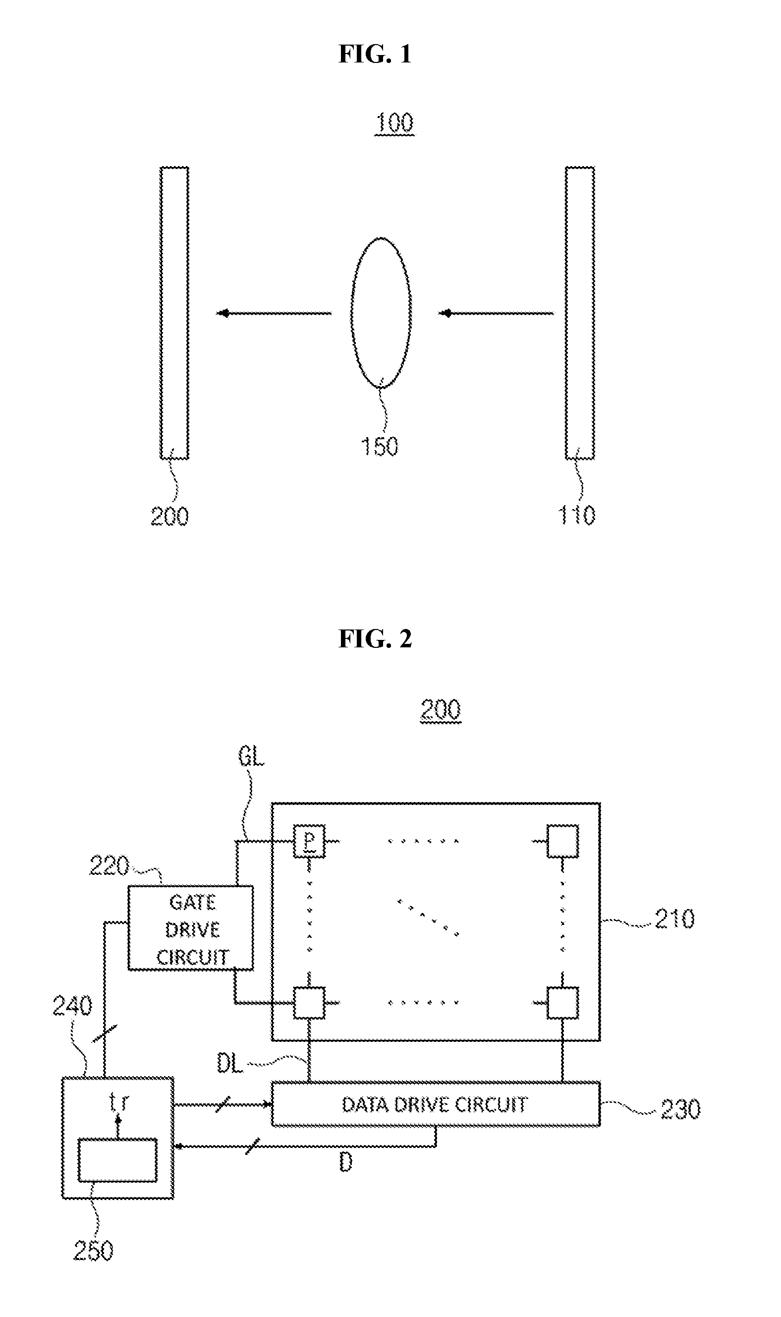
[0032]As an imaging device 100 according to the present invention, an imaging device that acquires images by radiating various forms of light, such as X-rays, visible light, and the like, may be used, but an X-ray imaging device for acquiring X-ray images is taken as an example for the convenience of description.

[0033]The imaging device 100 may include an X-ray radiation device 110 for generating an X-ray and radiating it onto an object to be checked 150, and an image sensor 200 for detecting the X-ray, having passed through the object 150.

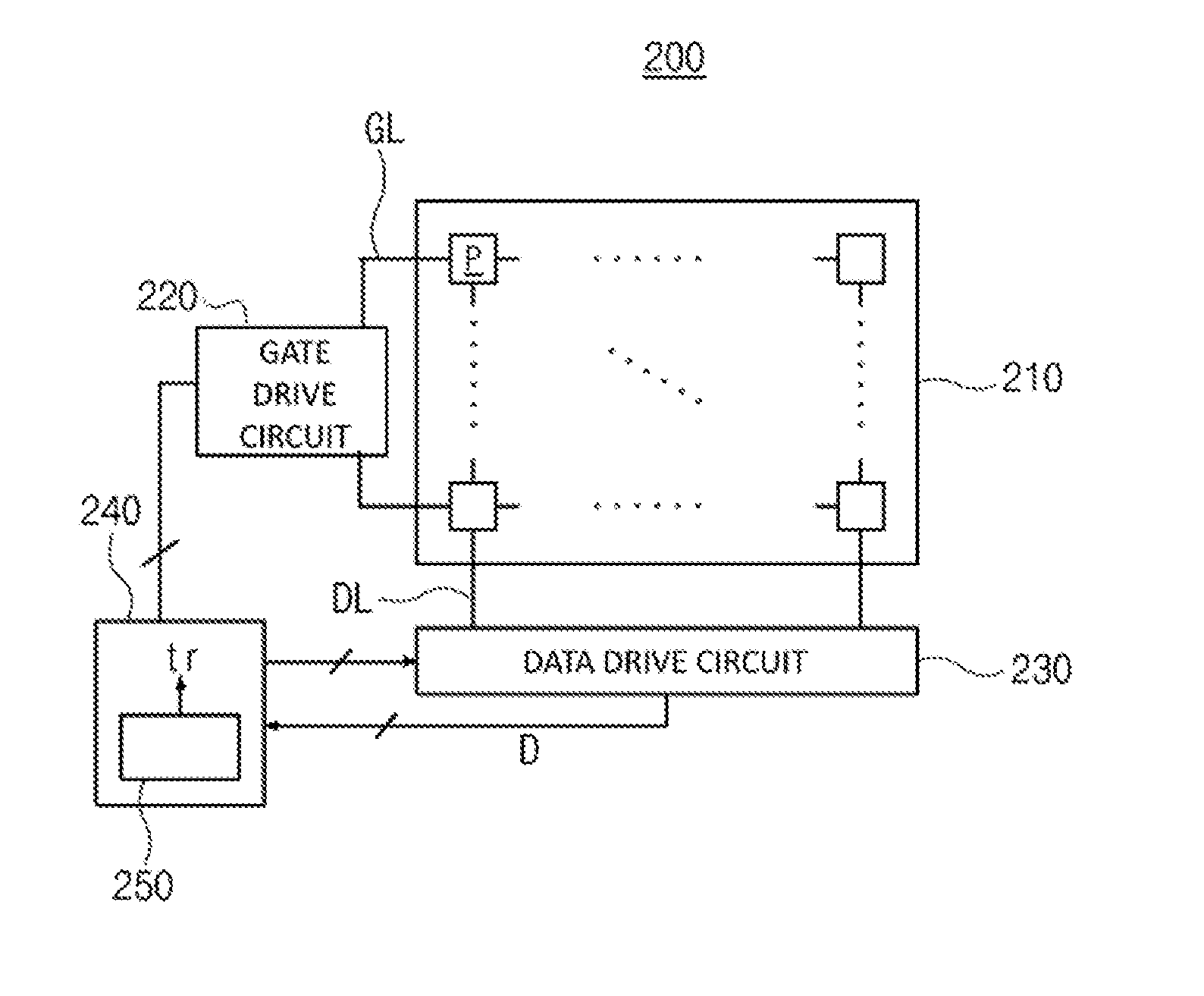
[0034]Here, the image sensor 200 is a sensor that operates through an automatic trigger method, in which whether an X-ray is radiated is autonomously detected and a trigger signal tr is generated based on the result of detection. Accordingly, the image sensor 200 does not need to communicate with the X-ray radiation device 110 for transmission of a synchronization signal.

[0035]Meanwhile, as the image sensor 200, an image sensor using a direct conv...

second embodiment

[0067]FIG. 5 illustrates the timing of application of a gate signal for driving an image sensor according to the present invention.

[0068]The image sensor of the second embodiment may be configured to have the same components as the image sensor 200 of the first embodiment.

[0069]Meanwhile, referring to the timing of application of a gate signal according to the second embodiment, when a trigger signal is generated by the radiation of the X-ray, a gate signal applied on a per-row line basis may be sequentially switched to a turn-off level (that is, the gate signal falls to the turn-off level) from the time point at which the trigger signal is generated (from the start of the charge accumulation period).

[0070]In this case, the actual time period during which charges are accumulated, that is, the time period toff, during which a signal having a turn-off level is applied between the time at which the X-ray is radiated and the time at which image data are read out, is the same for all of ...


PUM


Abstract

Disclosed is a method for driving an image sensor based on an automatic trigger method, in which pixels are arranged in the form of a matrix along row lines and column lines. The method includes, during an X-ray sensing period, continuously applying a gate signal having a turn-on level to all of the row lines of the image sensor and periodically reading out data from the all of the row lines; determining whether an X-ray is radiated by comparing the periodically read out data with reference data; generating a trigger signal when it is determined that an X-ray is radiated; and acquiring image data, generated by radiating the X-ray, according to the trigger signal.

Description

CROSS REFERENCE TO PRIOR APPLICATION[0001]The present application claims priority under 35 U.S.C. §119 to Korean Patent Application No. 10-2015-0093307 (filed on Jun. 30, 2015).BACKGROUND OF THE INVENTION[0002]Field of the Invention[0003]The present invention relates generally to an image sensor and, more particularly, to an automatic trigger-based image sensor, which is capable of automatically determining whether an X-ray is radiated.[0004]Description of the Related Art[0005]A digital image sensor is a device for detecting an external optical image signal and converting it into an electrical signal. Particularly, the digital image sensor is mainly used for an X-ray imaging device.[0006]In the image sensor, pixels, each of which is a unit for detecting an X-ray, are arranged in the form of a matrix along row lines and column lines. Here, each of the pixels has a photoelectric conversion element for converting the X-ray radiated from an X-ray radiation device into an electrical sign...

Claims


Application Information

Patent Timeline
Patent Type & Authority Applications(United States)
IPC IPC(8): H01L27/146G01T1/20
CPCH01L27/14659H01L27/14663H04N5/32G01T1/20
Inventor JUNG, BONG JOHWANG, KANG MIN
Owner RAYENCE
Why Eureka
Try Eureka