System and method for improved frequency/phase error tracking in high-speed high-frequency communication

a high-frequency communication and frequency/phase error technology, applied in the field of high-speed communication, can solve the problems of inefficient system, inability to estimate residual frequency error, and use a similar structure to achieve good performance for higher-frequency systems, so as to improve residual frequency error and phase noise estimation

Active Publication Date: 2010-01-07
KONINKLIJKE PHILIPS ELECTRONICS NV
View PDF20 Cites 18 Cited by
  • Summary
  • Abstract
  • Description
  • Claims
  • Application Information

AI Technical Summary

Benefits of technology

[0007]Therefore, the present invention has been made in view of the above problems. Accordingly, the present invention provides a single carrier modulation scheme suitable for use in high frequency communication systems that achieves improved residual frequency error and phase noise estimation. By using cyclically orthogonal constant amplitude pilot signals at the beginning (or end) of one or more SCBT blocks the need for long preambles at the beginning of the packet is precluded.

Problems solved by technology

Using conventional packet structures such as those used for WLANs for high-speed communications at high frequencies such as 60 GHz will not lead to an acceptable estimate of the residual frequency error.
However, using a similar structure will not lead to good performance for higher frequency systems (e.g., 60 GHz).
Unfortunately, this results in a very inefficient system.

Method used


Image

  • System and method for improved frequency/phase error tracking in high-speed high-frequency communication
  • System and method for improved frequency/phase error tracking in high-speed high-frequency communication
  • System and method for improved frequency/phase error tracking in high-speed high-frequency communication

Examples


Embodiment Construction

[0014]In the following discussion, numerous specific details are set forth to provide a thorough understanding of the present invention. However, those skilled in the art will appreciate that the present invention may be practiced without such specific details. In other instances, well-known elements have been illustrated in schematic or block diagram form in order not to obscure the present invention in unnecessary detail.

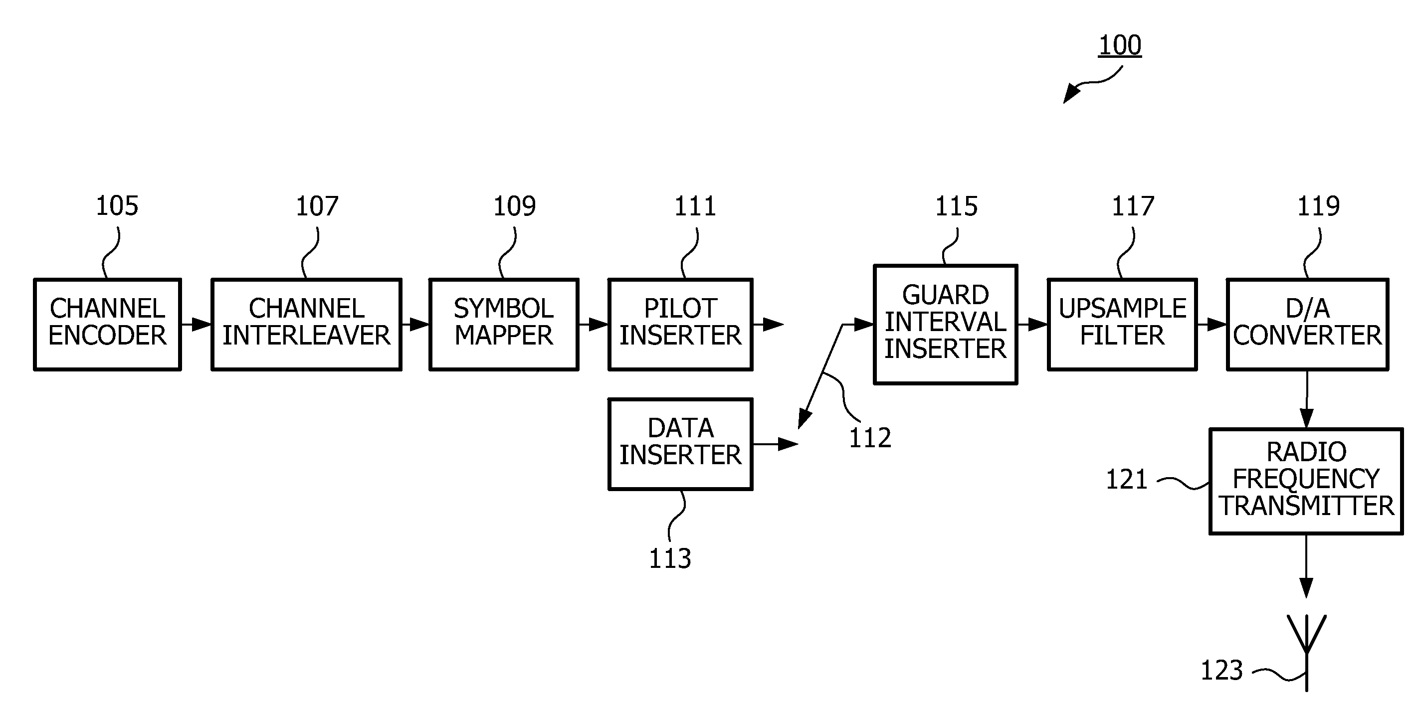
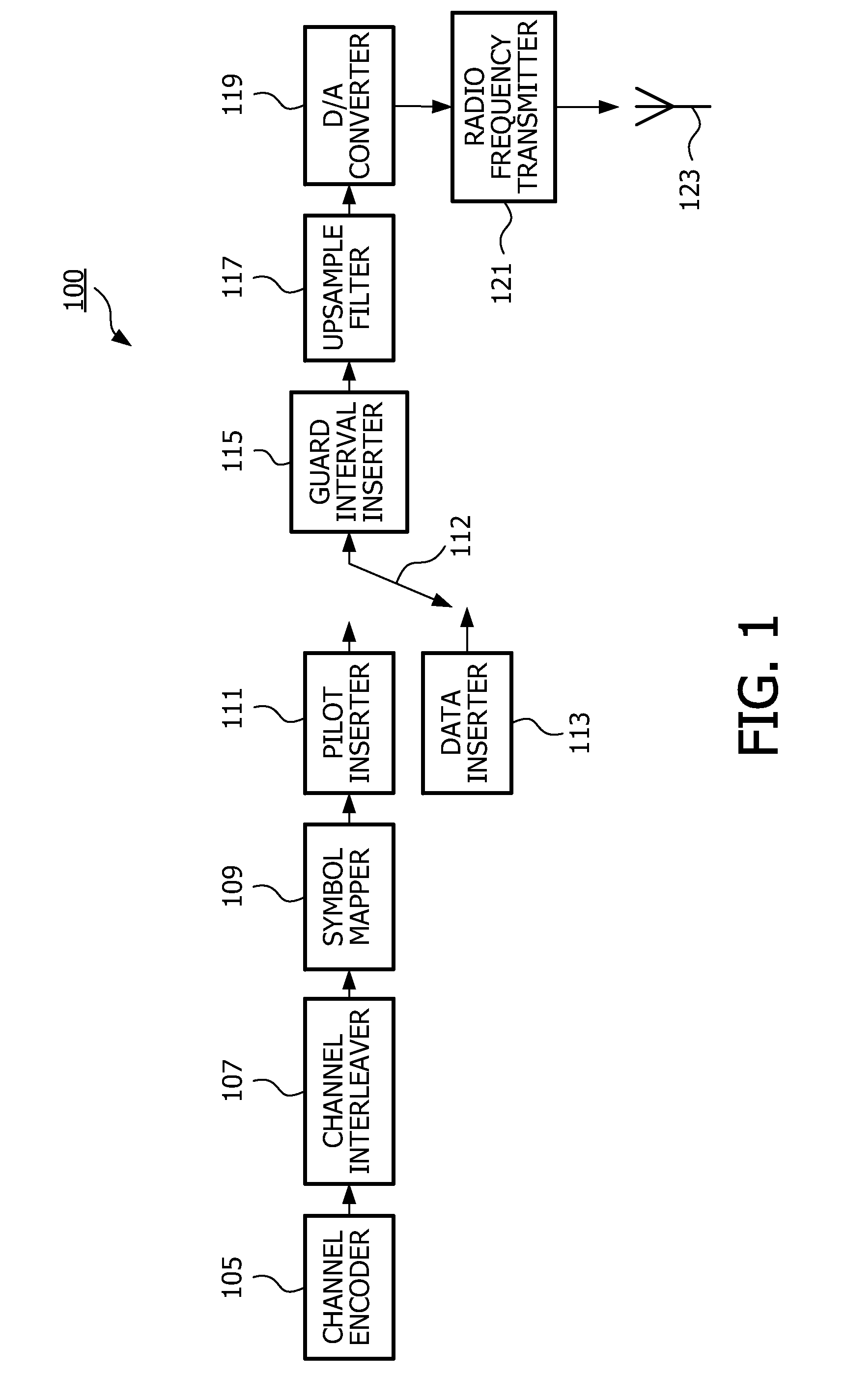
[0015]FIG. 1 is a functional block diagram of one embodiment of a data transmitter 100. As will be appreciated by those skilled in the art, the various functions shown in FIG. 1 may be physically implemented using a software-controlled microprocessor, hard-wired logic circuits, or a combination thereof. Also, while the functional blocks are illustrated as being segregated in FIG. 1 for explanation purposes, they may be combined in any physical implementation.

[0016]Data transmitter 100 includes a channel encoder 105, a channel interleaver 107, a symbol mapper 109, ...


PUM


Abstract

A single carrier modulation scheme suitable for use in high frequency communication systems is provided that achieves improved residual frequency error and phase noise estimation. At a transmitter, cyclically orthogonal constant amplitude pilot signals are inserted at the beginning (or end) of a plurality of SCBT blocks of a block coded data stream. At a receiver, a phase rotation of the received data stream is determined to remove a residual frequency error or to estimate the phase noise.

Description

CROSS REFERENCE TO RELATED APPLICATIONS[0001]This application claims the benefit of prior filed, co-pending U.S. provisional application: Ser. No. 60 / 885,137, filed on Jan. 16, 2007.BACKGROUND OF THE INVENTION[0002]1. Field of the Invention[0003]The invention relates generally to high speed communications and more particularly, but not exclusively, to a system and method for providing frequency / phase error tracking in a high-speed high-frequency communication system.[0004]2. Description of the Related Art[0005]Using conventional packet structures such as those used for WLANs for high-speed communications at high frequencies such as 60 GHz will not lead to an acceptable estimate of the residual frequency error. This is mainly because conventional packet structures contain a pre-amble sequence only at the beginning of the data. The use of such structures leads to performance that is adequate for lower frequency systems (e.g., 5 GHz) as the expected frequency error will not exceed 200 ...

Claims


Application Information

Patent Timeline
Patent Type & Authority Applications(United States)
IPC IPC(8): H04B17/00H04L27/00
CPCH04L5/0007H04L5/0048H04L27/2692H04L27/2657H04L27/2607H03M13/27H04L27/12H04L27/20H04B1/62
Inventor BIRRU, DAGNACHEWSEYEDI-ESFAHANI, SEYED-ALIREZA
Owner KONINKLIJKE PHILIPS ELECTRONICS NV
Why Eureka
Try Eureka