
Apparatus For Performing a Reaction In a Droplet and Method of Using the Same

a technology of apparatus and droplet, which is applied in the field of apparatus for performing a reaction in a droplet and a method of using the same, can solve the problems of limiting the freedom and flexibility of liquid handling for addition and mixing of different reagents, and not only the problem of protein adsorption

Active Publication Date: 2010-01-07
AGENCY FOR SCI TECH & RES
View PDF28 Cites 30 Cited by
  • Summary
  • Abstract
  • Description
  • Claims
  • Application Information

AI Technical Summary

Benefits of technology

The present invention provides an apparatus and method for processing biological and chemical samples in liquid droplets. The apparatus includes a processing compartment, a base, and at least one circumferential wall, with an inlet member located on the top of the processing compartment. The invention allows for the efficient processing of samples by using a droplet inlet channel with a contraction, which helps to stabilize the droplets and prevents them from splashing or evaporating during processing. The method also includes using a medium that is immiscible with the liquid droplet, which further enhances the stability of the droplets during processing. The technical effects of the invention include improved accuracy and efficiency in processing samples and reduced risk of contamination.

Problems solved by technology

However, achieving reproducibility, consistency and uniformity of differential surface coatings and establishing good quality control are a continuous challenge in the production environment.
Protein adsorption is furthermore not only a problem occurring at solid-water, but also at air-water and, where applicable, oil-water interfaces.
A further problem in the use of microdevices, particularly during incubation at for instance 37° C., prolonged storage and extended sample preparation using for instance large numbers of multiwell plates for screening purposes is evaporation.
Additionally, the freedom and flexibility of liquid handling for addition and mixing of different reagents become limited upon miniaturization.
In a lab-on-a-chip device, the fluidic circuit generally needs to be preprogrammed accordingly in advance, and it is inconvenient, if not infeasible, to add a specific reagent to a specific position as needed.

Method used


Image

  • Apparatus For Performing a Reaction In a Droplet and Method of Using the Same
  • Apparatus For Performing a Reaction In a Droplet and Method of Using the Same
  • Apparatus For Performing a Reaction In a Droplet and Method of Using the Same

Examples


example 1

Chip and Chip Holder of the Apparatus

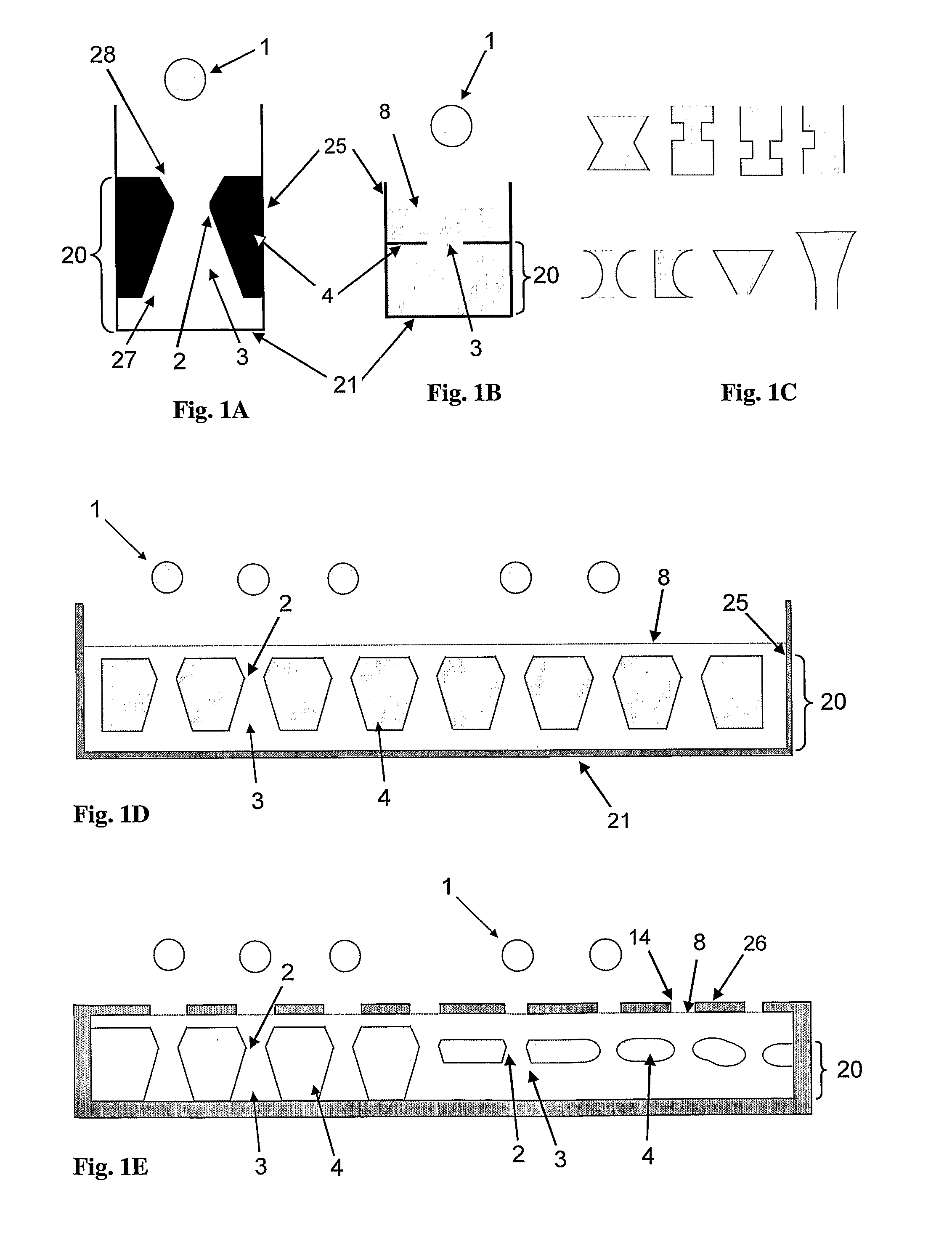
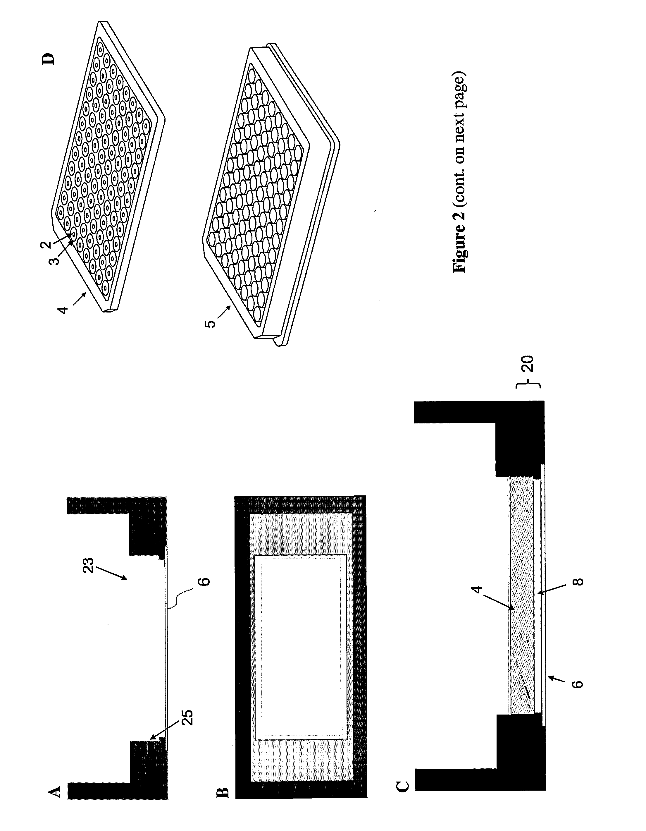
[0114]The present example illustrates embodiments of a chip and a chip holder of a apparatus of the invention, in which a chip is positioned in a pocket of the holder and immersed in an immiscible medium. Depending of the liquid of the droplet and the immiscible medium used, the chip is made of an organic, inorganic or metallic substrate such as plastic, glass, silicon, or stainless steel, and has an array of droplet inlet channels of hour glass shape. The size of a model chip depicted in FIG. 2F is 37.8 mm×17.8 mm and has a 19×10 array of droplet inlet channels, which posses a maximum diameter of 800 μm and a contraction diameter of 300 μm. The profile of the droplet inlet channels corresponds to the first profile depicted on the upper left of FIG. 1C. A further chip has an array of droplet inlet channels of cylindrical shape, where the diameter of droplet inlet channel varies throughout the chip. The respective profile corresponds to the second...

example 2

Liquid Handling

[0116]The immiscible medium may be a liquid, which is dispensed into the reservoir of a chip holder (cf. Example 1) so that it just fills half of the reservoir. Immiscible liquid can be mineral oil, silicone oil or perfluorocarbon liquid with or without appropriate hydrocarbon or perfluorocarbon surfactants. In most tests a perfluorocarbon liquid containing 0-10% perfluorocarbon-ethylene glycol surfactants was used. More specifically, perfluorocarbon liquid can be perfluorodecalin or Fluorinert™ available from 3M. The perfluorocarbon-ethylene glycol surfactant can be a compound with a structure of CF3(CF2)m—(CH2)n—(OCH2CH2)k—OH, in which m is an integer from 3 to 100, n is an integer from 0 to 10, and k is an integer from 1 to 200. In the compounds used typically m was an integer of 7-9, n an integer of 1-4 and k an integer of 1-200 (cf. Roach et al. supra, in particular the ‘supporting information’). Upon addition of perfluorocarbon liquid, a chip is placed in a pock...

example 3

Electric Field for the Handling of Droplets

[0119]An electric field, including an electrostatic field, is a typical method for controlling a droplet in a perfluorocarbon liquid. Electrodes can be configured in many ways depending on the specific needs. In one configuration, an electro-chip with a footprint identical to an array of droplet inlet channels is placed on a sample chip and used as an electrode (FIG. 4C). The electro-chip can be made of a metal such as aluminium or stainless steel or a non-metal such as glass or silicon with metal coating. The other electrode of a flat slide is placed underneath a chip holder. The voltage applied to an electrode varies depending on the distance between the electrodes and the sizes of the droplet and droplet inlet channel. In general, a higher voltage is required as (a) the distance between electrodes increases, and as (b) the ratio of droplet size over neck diameter of a droplet inlet channel increases. For example, a voltage of 3 kV is req...


PUM

PropertyMeasurementUnit
volumeaaaaaaaaaa
volumeaaaaaaaaaa
volumeaaaaaaaaaa

Abstract

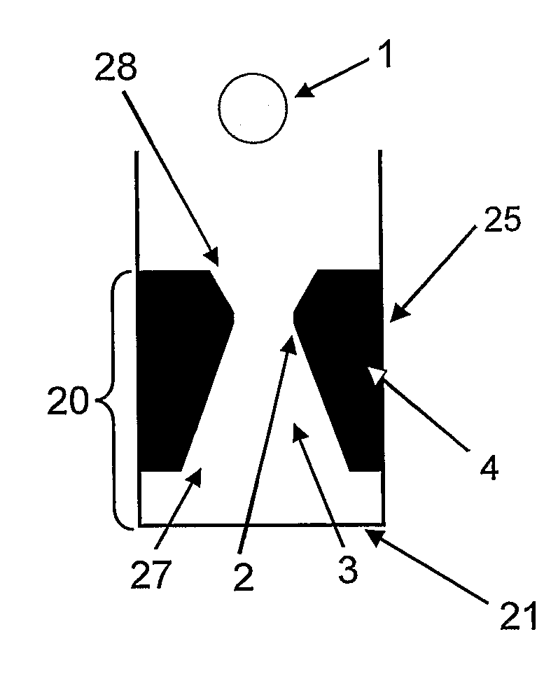
An apparatus for processing a biological and / or chemical sample in a liquid droplet (1) is provided. The apparatus includes a processing compartment (20), a base (21) and at least one circumferential wall (25). The processing compartment (20) is defined by at least a part of the base (21), at least a part of the circumferential wall (25) and an inlet member (4). The inlet member (4) is located on top of the processing compartment (20), and includes at least one droplet inlet channel (3), which extends through the inlet member (4) and includes a contraction (2) between the inlet opening (28) of the droplet inlet channel (3) to the environment and the outlet opening (27) to the processing compartment (20). There is furthermore provided a method of processing a biological and / or chemical sample in a liquid droplet (1). The method includes disposing a medium into the processing compartment (20) of the apparatus of the invention that is immiscible with the liquid droplet (1), so that the contraction (2) is immersed in the medium. The droplet (1) is disposed into the droplet inlet channel (3) such that it is located below the contraction (2) of the droplet inlet channel (3). A process is performed on the biological and / or chemical sample in the droplet (1).

Description

FIELD OF THE INVENTION[0001]The present invention relates to an apparatus and a method for processing a biological and / or chemical sample in a liquid droplet.BACKGROUND OF THE INVENTION[0002]Miniaturization continues to play a role of an enabling technology in bioinstrumentation by offering key advantages to research in life sciences and pharmaceuticals. Most importantly, it allows significant reduction of research expense by decreasing the consumption of expensive reagents. Furthermore, it enables the study of proteins and compounds that are rare or too expensive to run at a bulk scale. Miniaturization of assays facilitates the increase in through-put and density of information, and can lead to better data quality and less sample variation in a series of assays.[0003]Efforts on miniaturization in bioinstrumentation have delivered a number of revolutionary tools and opened a new venue in life science and pharmaceutical research. Notably, miniaturization enabled large-scale analysis ...

Claims


Application Information

Patent Timeline
Patent Type & Authority Applications(United States)
IPC IPC(8): G01N1/00
CPCB01L3/0268B01L3/5085B01L2200/026B01L2200/0673G01N1/28B01L2400/027G01N2035/00158G01N2035/1034G01N2035/1037B01L2300/0609
Inventor KIM, NAM YONGYING, Y. JACKIELEE, YONG YEOWLECK, KWONG JOO
Owner AGENCY FOR SCI TECH & RES
Learn More