Fastening Clamp

a technology of fastening clamps and clamping rods, which is applied in the direction of screws, nuts, sheets, etc., can solve the problem of not having the possibility of adjustment in the previously known fastening clamp, and achieve the effect of low overall heigh

Active Publication Date: 2010-01-07
A RAYMOND & CO
View PDF13 Cites 2 Cited by
  • Summary
  • Abstract
  • Description
  • Claims
  • Application Information

AI Technical Summary

Benefits of technology

[0005]It is an object of the invention to disclose a fastening clamp of the kind described ab...

Problems solved by technology

There is, however, no possibility for adju...

Method used


Image

  • Fastening Clamp
  • Fastening Clamp
  • Fastening Clamp

Examples


Embodiment Construction

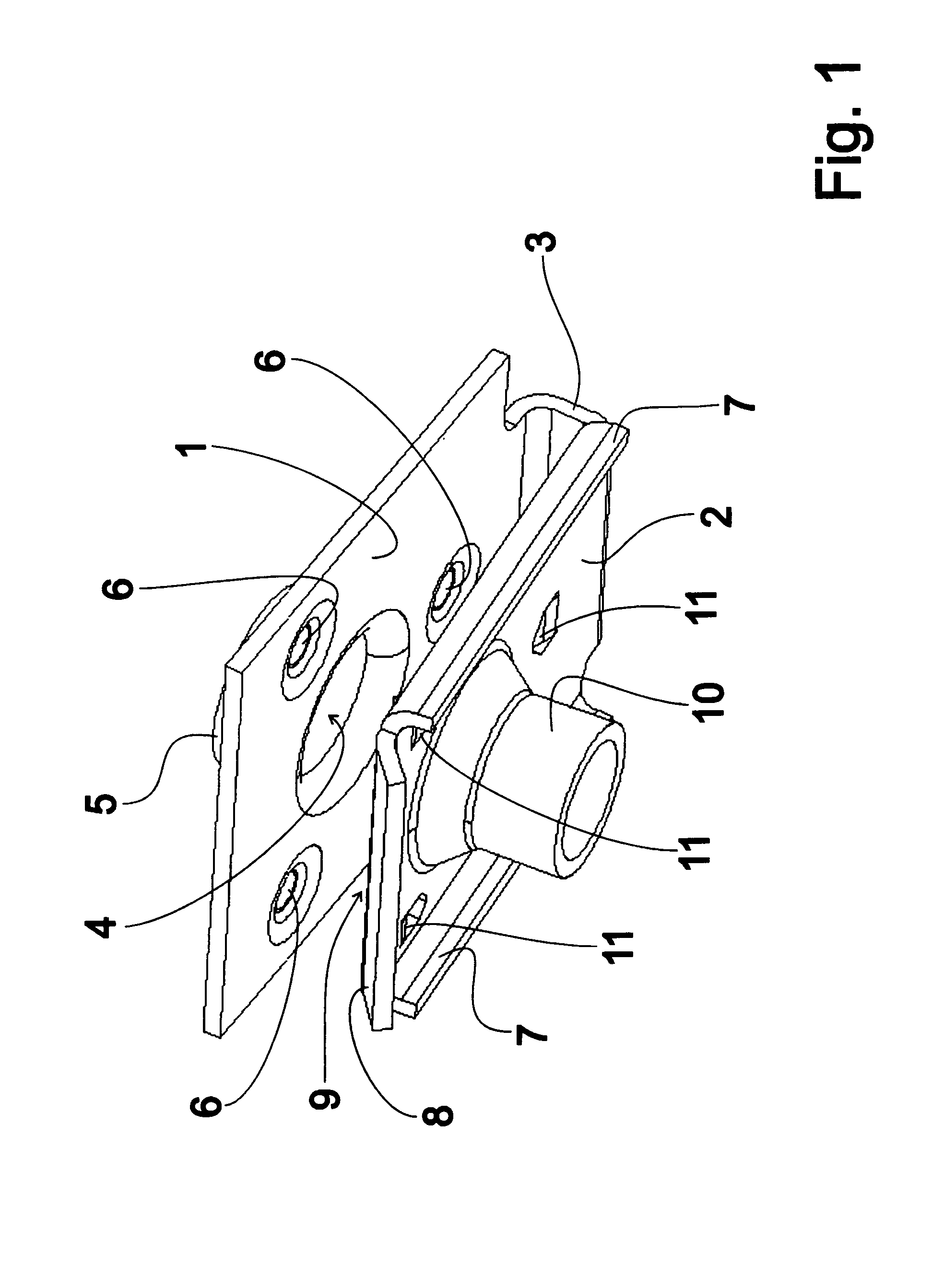
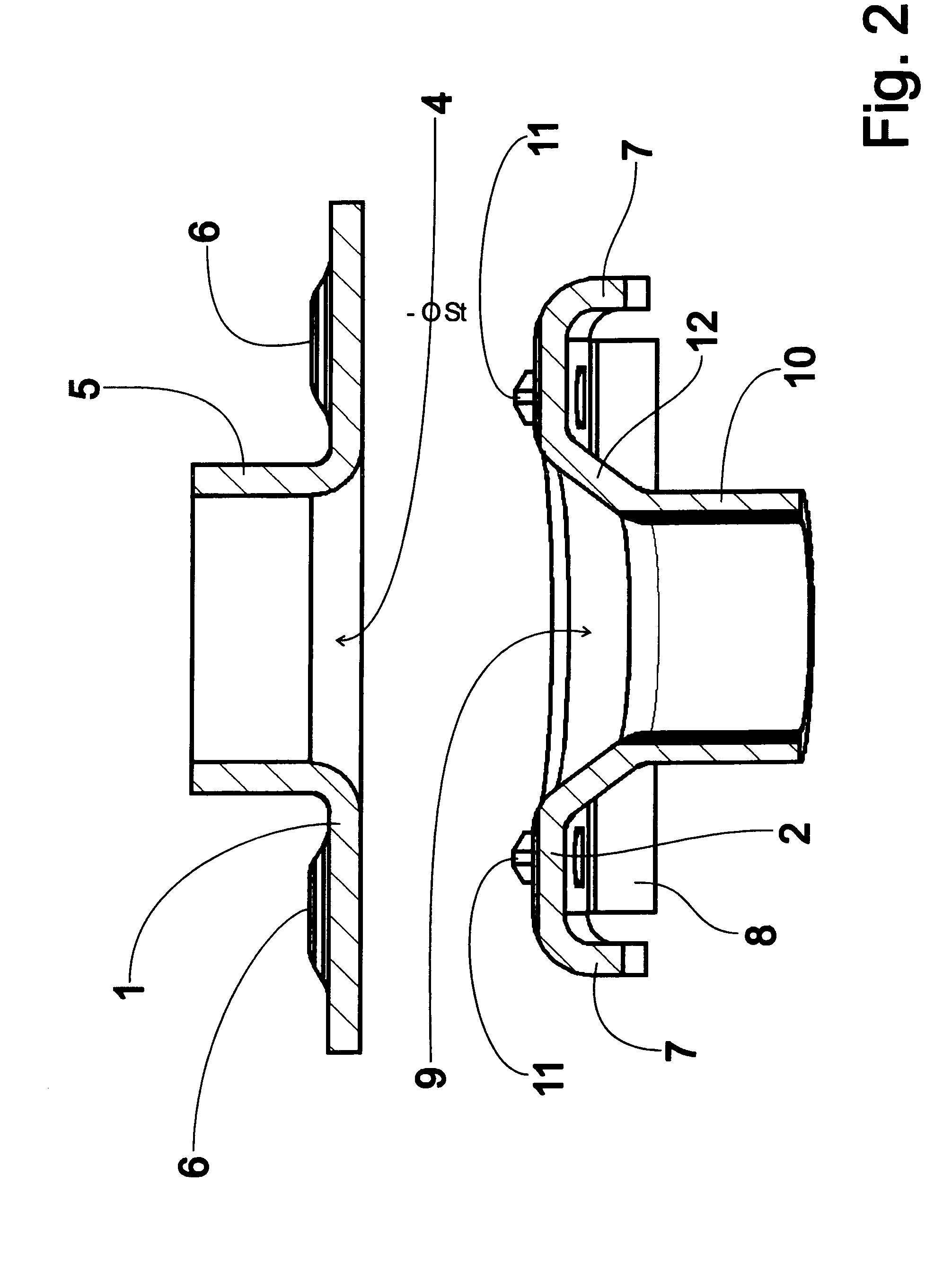
[0014]FIG. 1 shows a perspective view of an exemplary embodiment of a fastening clamp according to the invention, which has an essentially rectangular, flat pass-through leg 1 and a likewise rectangular threaded leg 2 arranged opposite to the pass-through leg. The pass-through leg 1 and the threaded leg 2 are mutually connected via a connecting section 3 positioned on the narrow side edges.

[0015]The pass-through leg 1 has a pass-through recess 4, on whose edge area is positioned a pass-through sleeve 5, which extends away from the pass-through leg 1. A multitude of elevations 6, which project over the side of the pass-through leg 1 that faces away from the threaded leg 2, are embossed in the pass-through leg 1 around the pass-through sleeve 5.

[0016]The threaded leg 2 has lateral ribs 7 as reinforcement at its longer side edges, which are bent essentially at a right angle and face away from the pass-through leg 1. On the short side edge, the threaded leg 2 is configured with a diagon...


PUM


Abstract

A fastening clamp for connecting a carrier part (13) and an add-on part (14) has a plug-through leg (1), with a plug-through sleeve (5), and a threaded leg (2), which is connected to a thread unit (10). The plug-through sleeve (5) extends away from the threaded leg (2) and has an effective overall height which is greater than the thickness of an add-on part (14). Engagement elements (11) are present on that side of the thread leg (2) which is directed towards the plug-through leg (1). In a pre-assembly arrangement, the legs (1, 2) are spaced apart by a distance which is large enough to allow a carrier part (13) to be positioned between the legs (1, 2) such that it is essentially free of engagement with the engagement elements (11), in which case, once a screw has been screwed into an end position, the engagement elements (11) thus engage with the carrier part (13) such that the fastening clamp is connected in a non-displaceable manner to the carrier part (13). This achieves a certain degree of positioning freedom on the carrier part (13) and, for tolerance-compensating purposes, movement of the add-on part (14).

Description

TECHNICAL FIELD[0001]The invention concerns a fastening clamp for connecting a carrier part and an add-on part.BACKGROUND ART[0002]A fastening clamp such as this is known from FR 2 762 882 A1. The already known fastening clamp for connecting a carrier part and an add-on part via a pass-through leg having a pass-through sleeve, through which a screw can be guided, and a threaded leg arranged opposite to the pass-through leg, which is connected via a film hinge to a fitting plate opposite to the pass-through leg, which supports a spacer sleeve that extends in the direction of the pass-through leg. A threaded unit, which is aligned facing away from the pass-through leg and into which a screw can be screwed, is formed on the threaded leg. The pass-through sleeve extends away from the threaded leg and has an effective overall height that is greater than the thickness of an add-on part. Engagement elements are also configured, and the pass-through leg as well as the threaded leg have a di...

Claims


Application Information

Patent Timeline
IPC IPC(8): A44B21/00
CPCF16B5/0225F16B5/0266Y10T24/44504Y10S411/999Y10S411/97F16B37/043F16B2/02F16B2/12F16B2/00
Inventor DE GELIS, VINCENT
Owner A RAYMOND & CO
Why Eureka
Try Eureka