
Data processing system, data processing method, and program

a data processing system and data processing technology, applied in the field of data processing system, data processing method, program, etc., can solve the problems of large threat to the employing system, high processing load, and inability to achieve prior ar

Inactive Publication Date: 2009-12-31
MITSUBISHI ELECTRIC CORP
View PDF8 Cites 58 Cited by
  • Summary
  • Abstract
  • Description
  • Claims
  • Application Information

AI Technical Summary

Benefits of technology

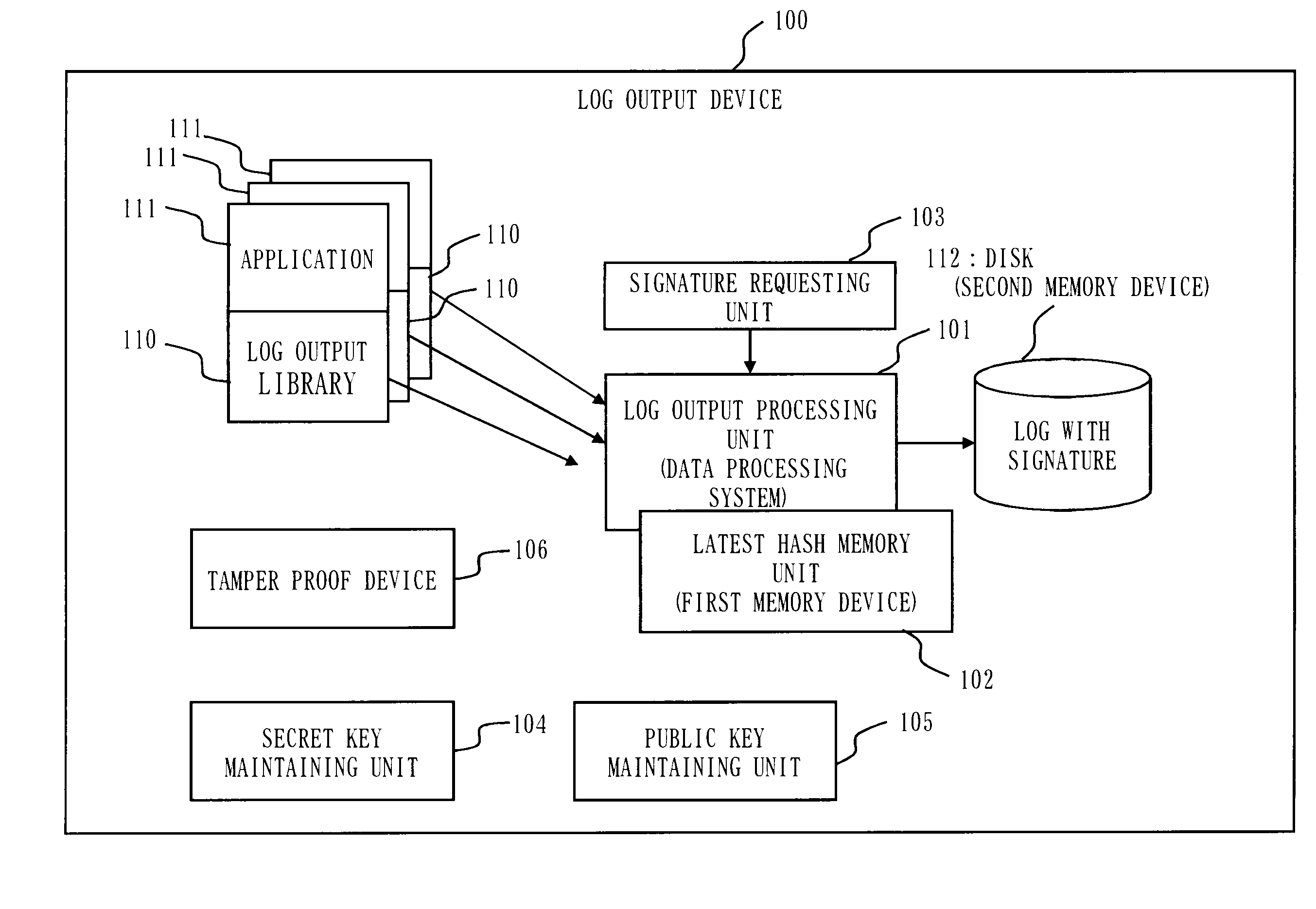
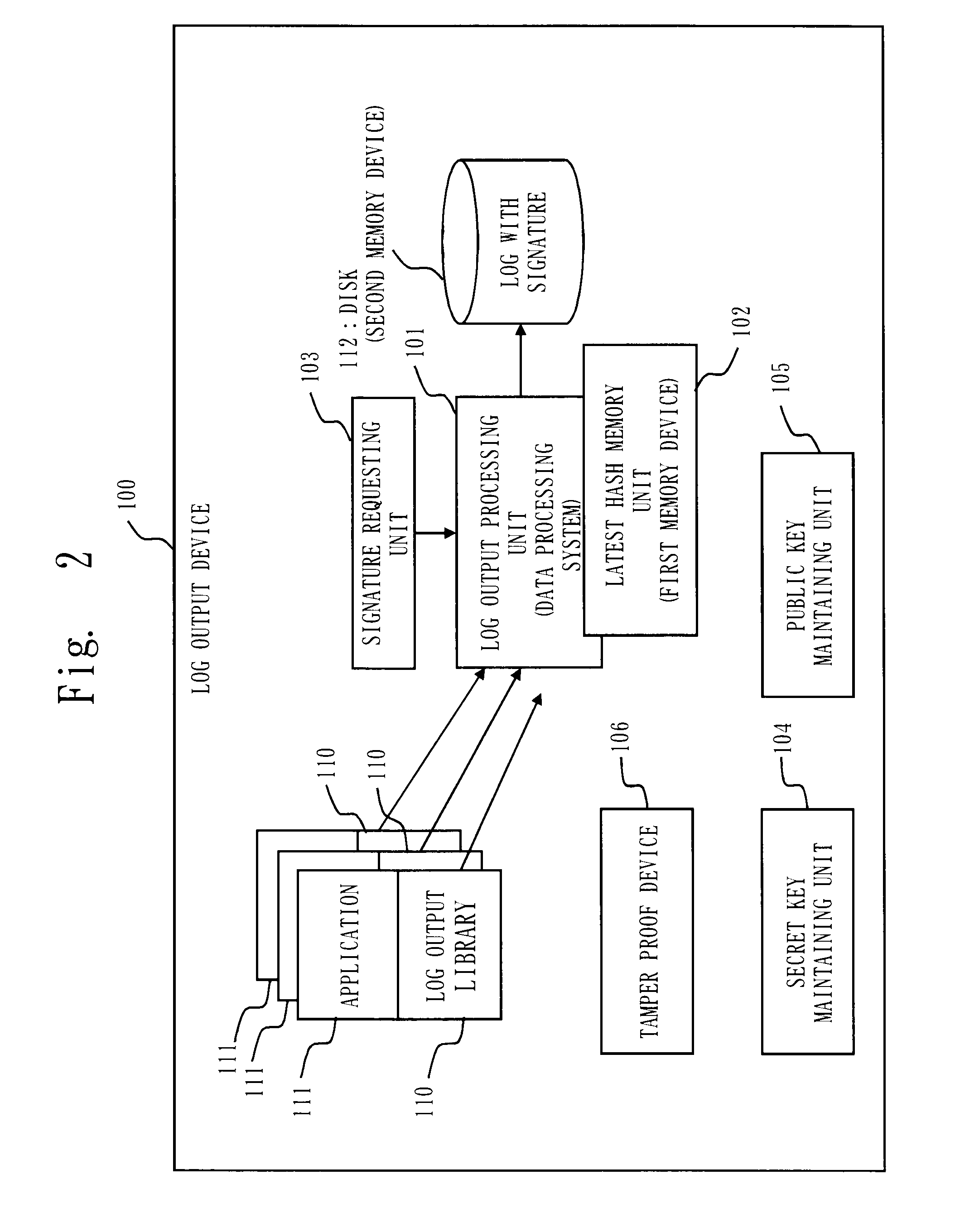
[0051]As discussed above, according to the present invention, by storing in the first memory device a copy of the first hash value and the second hash value of storage data to be stored in the second memory device, and when new data is outputted, by comparing the last first hash value and the last second hash value stored in the second memory device with the copy of the last first hash value and the last second hash value stored in the first memory device, it is possible to detect tampering, so that it becomes unnecessary to append a signature to all data to be stored in the second memory device, which reduces the load of signature process and prevents increase of data amount because of the signatures.
[0052]Further, in addition to solving the problems of the conventional art, the present invention brings effect to have a function to prevent undetectable tampering, and when tampered, to narrow a possibly tampered position as narrow as possible.PREFERRED EMBODIMENTS FOR CARRYING OUT THE INVENTIONEmbodiment 1(Basic Configurations of a Log Output Device and a Log Output Program and Signature Appendage at Every Certain Number of Lines Interval and at Every Certain Time Interval)
[0053](Format of a Log and Formation of a Hash Chain)
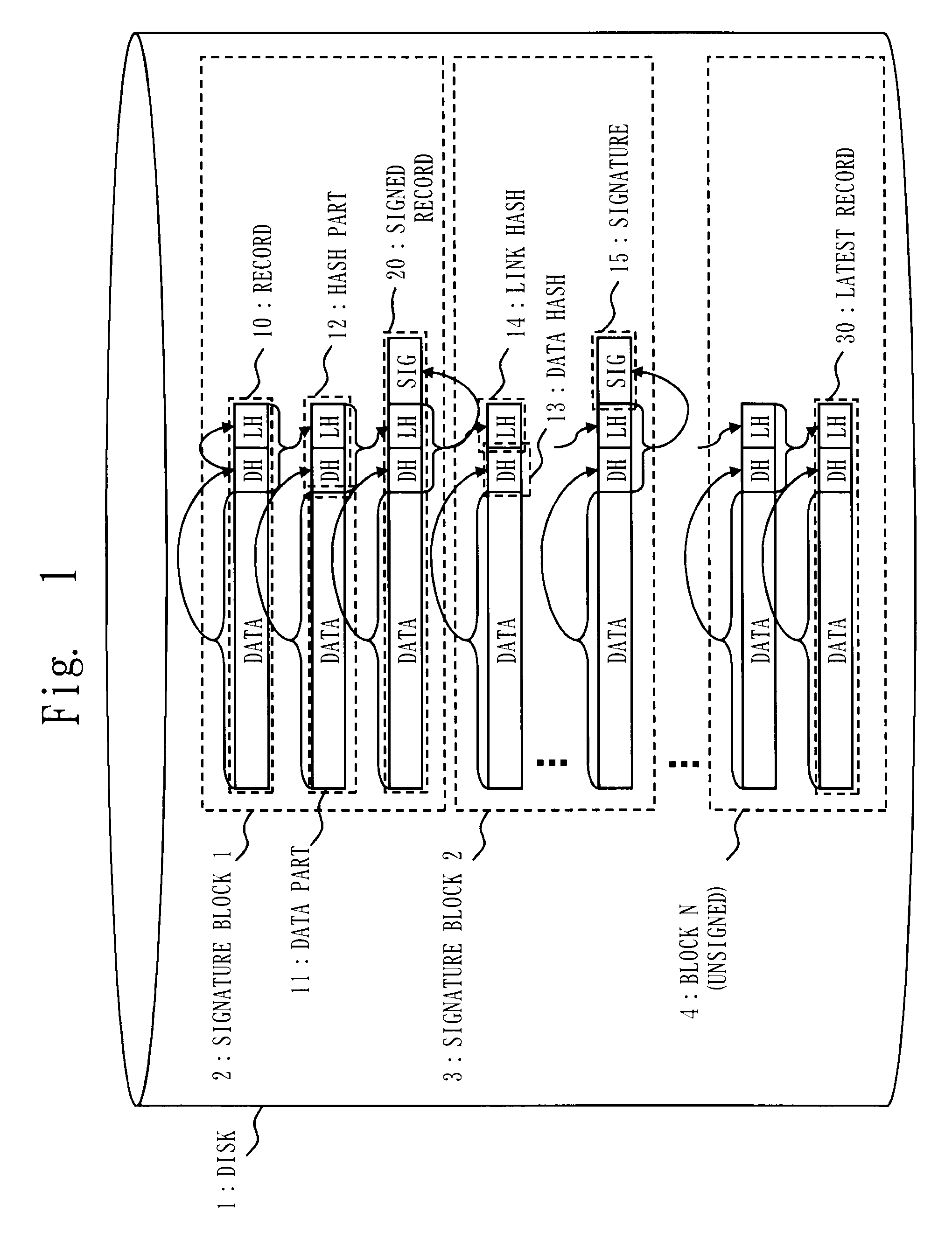
[0054]FIG. 1 is a block diagram showing a format of a log for a log output device according to the first embodiment.
[0056]A record 10 (or simply record, hereinafter) is formed by a data part 11 and a hash part 12. Here the data part 11 is a log message body.
[0057]Further, the hash part 12 is formed by a data hash (DH) 13 which is a hash value of the data part 11, and a link hash (LH) 14 which is a further hash value of the hash part 12 of the previous record 10 (here, for the initial record, it is assumed that the hash of the data hash is the link hash).

Problems solved by technology

Like this, since the log has been playing an important role in all systems nowadays, tampering of log data is a large threat for employing the system, and it has been an important problem to secure the integrity (to certify that it is not tampered) of the log.
Since the signature process (secret key operation) requires a large quantity of calculation (approximate 100-1000 times of hash calculation), the processing load becomes very high under circumstance that record is frequently generated, which causes a problem that this prior art is not practical.
Further, since the signature is appended to each record, there is another problem that the whole size of data becomes large (if RSA (registered trademark) (Rivest Shamir Adleman) 2048-bit key is used for the signature, the data size is increased by 256 bytes per record; namely, about 342 bytes if Base 64 transformation is carried out).
Thus, it is not possible to concretely obtain the advantage of the idea.
However, according to this prior art, the signature is appended only at the final stage after some amount of logs are accumulated, so that there is a problem that it is impossible to find a tampering if the data is tampered before the logs are accumulated to reach the some amount (because of character of data such as a log, it is necessary to always append a signature instead of appending only at the final stage).

Method used


Image

  • Data processing system, data processing method, and program
  • Data processing system, data processing method, and program
  • Data processing system, data processing method, and program

Examples


embodiment 1

(Basic Configurations of a Log Output Device and a Log Output Program and Signature Appendage at Every Certain Number of Lines Interval and at Every Certain Time Interval)

[0053](Format of a Log and Formation of a Hash Chain)

[0054]FIG. 1 is a block diagram showing a format of a log for a log output device according to the first embodiment.

[0055]A disk 1 records / stores a log.

[0056]A record 10 (or simply record, hereinafter) is formed by a data part 11 and a hash part 12. Here the data part 11 is a log message body.

[0057]Further, the hash part 12 is formed by a data hash (DH) 13 which is a hash value of the data part 11, and a link hash (LH) 14 which is a further hash value of the hash part 12 of the previous record 10 (here, for the initial record, it is assumed that the hash of the data hash is the link hash).

[0058]The data hash (DH) 13 is an example of the first hash value, and the link hash (LH) 14 is an example of the second hash value.

[0059]A signed record 20 is a record formed b...

embodiment 2

[0171](Signature Appendage Based on Application Instruction and Log Transfer Request from the Outside)

[0172]In the present embodiment, another embodiment will be discussed, in which timing for appending a signature to the log on the disk is at the time of instruction by the application 111 and at the time of log transfer request from the outside.

[0173]Here, configurations of the log output device, the log output processing unit 101, log format, etc. are the same as ones discussed in the first embodiment, and description is omitted in the present embodiment.

[0174](Signature Appendage by Application Instruction)

[0175]Based on the configuration / operation explained in the first embodiment, the signature generating unit 1013 of the log output processing unit 101 can append signatures to the log at timing instructed by the application 111.

[0176]This can be implemented by configuring the device so that the application 111 requests the linked log output library 110 to output the log, and as...

embodiment 3

(Signature Appendage Based on Instruction of an Administrator or an Operator)

[0185]In this embodiment, another case will be explained, in which it is assumed a signature is appended to a log on a disk when an instruction is done by an administrator or an operator.

[0186]Here, the configuration of the log output device, the log output processing unit 101, the log format, etc. are the same as discussed in the first embodiment, and their descriptions will be omitted in this embodiment.

[0187]Based on the configuration / operation explained in the first embodiment, the signature requesting unit 103 of the log output processing unit 101 can append the signature to the log at timing when the signature request is issued from the administrator or the operator (a user of the log output device 100).

[0188]This can be implemented by configuring the device so that the signature requesting unit 103 receives the signature request from the administrator or the operator.

[0189]By this configuration, it i...


PUM


Abstract

A log output device and a program are provided, which append a signature to a log, prevent an undetectable tampering (alteration, insertion, deletion, etc.), and are able to narrow tampered position if tampered. The log output device forms a log record including a data part and a hash part, and outputs to a disk; the hash part is formed by combining a hash of the data part (data hash) and a hash of the hash part of the previous record (link hash); a signature is appended to only a part of records of a hash chain; when outputting the record to the disk, a copy of the hash part of the record is maintained on a process memory; when outputting next record, the hash part of the latest record on the disk and the hash part maintained on the process memory are compared; if they are matched, the record on the disk is determined as not being tampered, and if mismatched, the record is determined as tampered.

Description

TECHNICAL FIELD[0001]The present invention relates to, for example, a log in a contents distribution system or a company information system, and in particular, to technique to prevent undetectable tampering (alteration, wrong record insertion, deletion, etc.) and to secure integrity of the log by appending a signature to log data.BACKGROUND ART[0002]Nowadays, a “log” outputted from equipments or devices belonging to a system has increased its importance in a contents distribution system or a company information system.[0003]For example, in the contents distribution system, it has been carried out or will be carried out that the contents holder verifies whether sales of the contents is done within a licensed range (permitted sales amount, sales price, etc.) permitted for the contents provider (distributor) by the contents holder based on a log of the contents distribution system deployed and developed by the contents provider.[0004]Further, it has been carried out or will be carried ...

Claims


Application Information

Patent Timeline
Patent Type & Authority Applications(United States)
IPC IPC(8): G06F12/14G06F12/00G06F12/16G06F21/64G06F21/86
CPCG06F21/64G06F21/86G06F2221/2101H04L2209/60H04L9/3247H04L2209/38H04L9/3236H04L9/50
Inventor TSURUKAWA, TATSUYA
Owner MITSUBISHI ELECTRIC CORP
Learn More