
Reactor geometry and dry confinement for a nuclear reactor enabling the racquetball effect of neutron conservation dry confinement to be supported by the four-factor and six-factor formula

a nuclear reactor and reactor geometry technology, applied in the field of reactor geometry and dry confinement of nuclear reactors, can solve the problems of stumbling down the industry, unable to meet the needs of nuclear reactors, and unable to meet the requirements of nuclear reactors,

Inactive Publication Date: 2009-12-31
DAUVERGNE HECTOR A
View PDF2 Cites 12 Cited by
  • Summary
  • Abstract
  • Description
  • Claims
  • Application Information

AI Technical Summary

Benefits of technology

[0010]The present invention provides a portable nuclear-powered plant assembly including a nuclear core, and one or more confinement sections confining the nuclear core. The assembly further includes a fuel source including thorium

Problems solved by technology

Over the years, however, the U.S. nuclear industry has attempted to push ahead with vast, costly projects that carry with them an array of environmental, safety, and health risks.
These costs and risks have stunted its growth.
Indeed, the industry has come to a virtual standstill until 2003.
Now with new construction in sight, if again waste is ignored, the associated risks will have resulted in political opposition and public fears that will tend to block not only plant expansion, but development of new forms of nuclear power as well.
In the 1970s, dreams of energy surpluses based on nuclear power soon turned into shortages, but the energy shortages of the period were followed in the 1980s by a glut that clouded the energy issue.
Added to this problem is the depletion of the petroleum reserves needed to fuel power plants and a growing vehicle fleet.
Additionally, alternative energy technologies—such as solar, wind, and geothermal—are losing governmental support.
Indeed, the U.S. appears to be heading toward another energy crisis due to governmental policies, public fears of nuclear power, utility company shortsightedness, and corporate lack of incentives to either use alternative energy technologies or conserve energy.
Conventional nuclear power has its own set of drawbacks.
Specifically, nuclear reactors generate radioactive wastes that remain in diminishing intensity for several centuries.
No state within the U.S. has been willing to become the national repository for nuclear refuse.
This is a highly political, sensitive matter, and each state is grappling with its own methods of handling radioactive waste.
Because of waste storage concern, high costs, and inherent health risks, it appears that conventional nuclear energy-generating means are being rejected.
Moreover, there is fear of a meltdown that could release radioactivity, and concern that materials for nuclear weapons could be generated.
These fears have continually plagued the industry, and since the 1990s it has appeared doubtful that conventional nuclear power generation will be allowed to grow as a means to meet energy deficiencies.
Since all conventional energy-generating sources present grave hazards to public safety, health, and psychological well being, U.S. citizens are demanding a clean, safe, and domestically-produced energy source.
Since the most viable sources of alternative fuel are hydrogen and electricity, this demand cannot be fully enforced for the simple reason that both hydrogen and electricity are not energy sources but rather energy carriers that need a source of energy to start.
Nuclear energy has not been promoted as an alternative because the perceived risks have been amplified by political and environmentalist pressure.
However, experimental efforts to achieve such fusion have not been sustained.
There is little evidence, however, that indicates fusion will be a viable method of generating energy to solve either U.S. or worldwide fuel problems for at least 40 years.

Method used


Image

  • Reactor geometry and dry confinement for a nuclear reactor enabling the racquetball effect of neutron conservation dry confinement to be supported by the four-factor and six-factor formula
  • Reactor geometry and dry confinement for a nuclear reactor enabling the racquetball effect of neutron conservation dry confinement to be supported by the four-factor and six-factor formula
  • Reactor geometry and dry confinement for a nuclear reactor enabling the racquetball effect of neutron conservation dry confinement to be supported by the four-factor and six-factor formula

Examples


Embodiment Construction

[0042]While the present invention will be described with reference to a few specific embodiments, the description is illustrative of the invention and is not to be construed as limiting the invention. Various modifications to the present invention can be made to the preferred embodiments by those skilled in the art without departing from the true spirit and scope of the invention as defined by the appended claims. It will be noted here that for a better understanding, like components are designated by like reference numerals throughout the various figures.

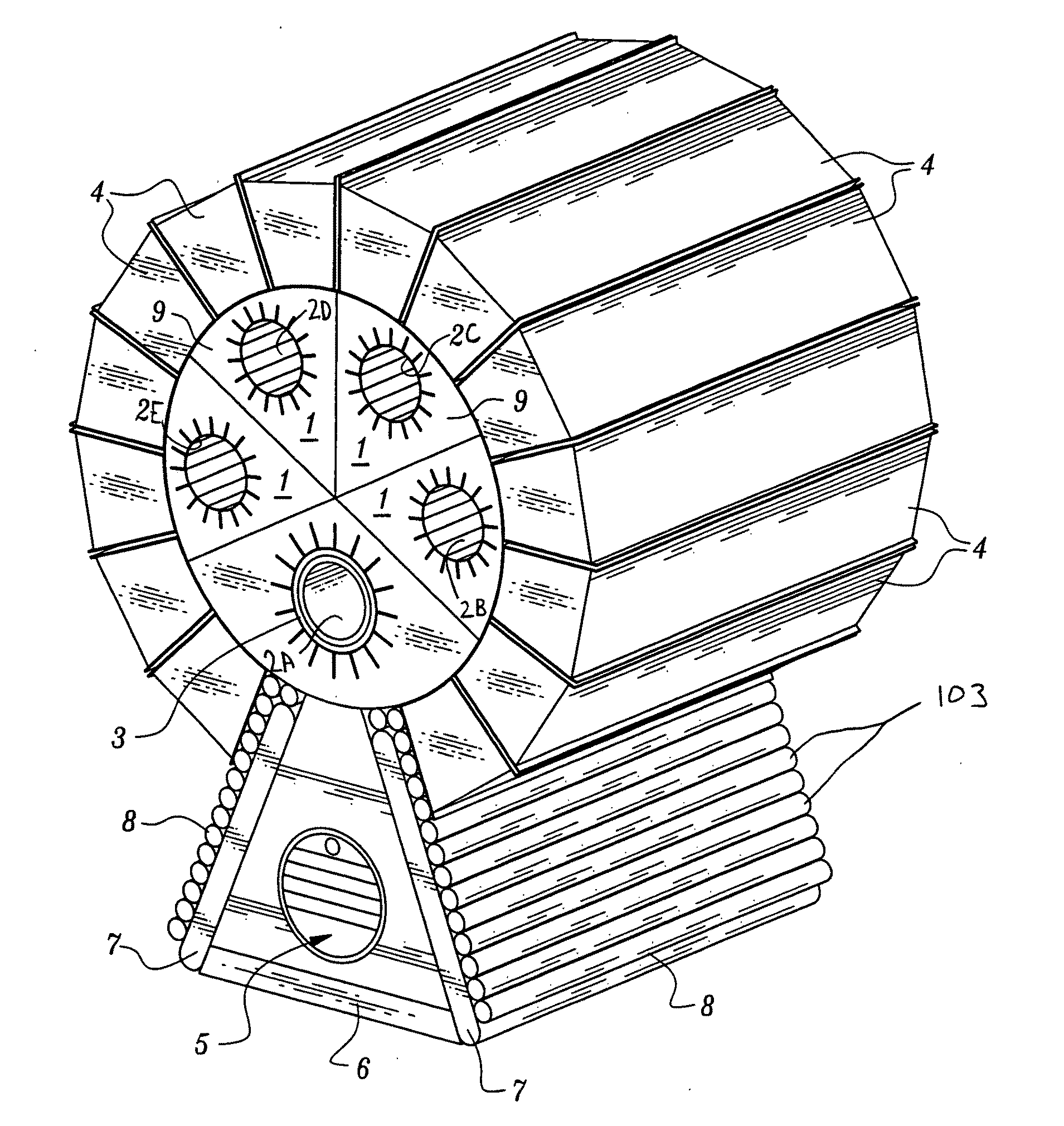
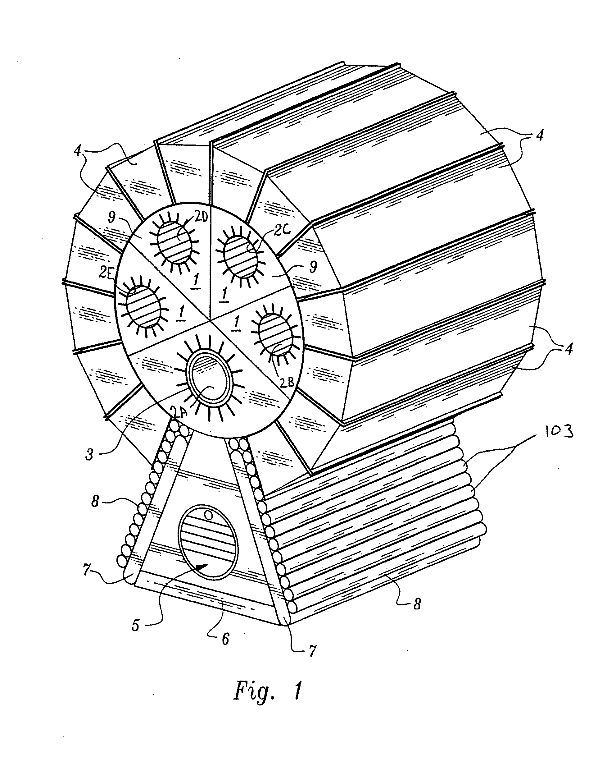
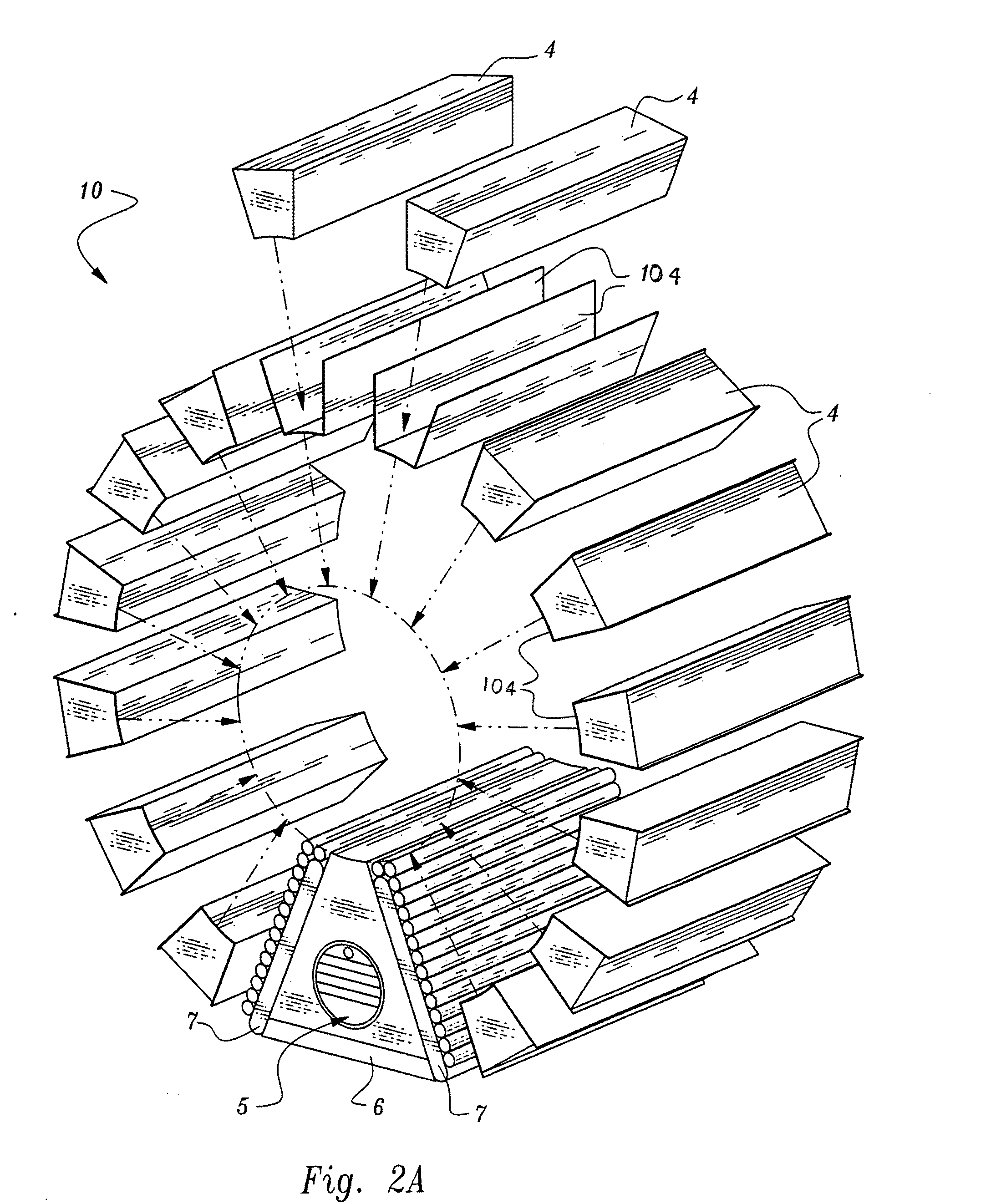
[0043]Referring to FIGS. 1-8, a portable nuclear-powered plant assembly including a nuclear core, and one or more confinement sections confining the nuclear core. The assembly further includes a fuel source including thorium / uranium-233, positioned in the nuclear core, to create a nuclear reaction. In another embodiment, the nuclear-powered plant assembly further includes a tank arrangement containing a material suitable for therma...


PUM


Abstract

A nuclear-powered plant of a portable type with a confinement section where the reaction takes place in a core having a reactive thorium / uranium-233 composition, and where an external neutron source is used as a modulated neutron multiplier for the reactor core output. The core is housed in a containment structure that radiates thermal energy captured in a multiple-paths heat exchanger. The exchanger heat energy output is put to use in a conventional gas-to-water heat exchanger to produce commercial quality steam.

Description

RELATED APPLICATION DATA[0001]The present application claims priority under 35 U.S.C. § 119 to U.S. Provisional Application Ser. No. 60 / 450,506 (Attorney Docket No. DAUVP001P), entitled “DRY CONFINEMENT FOR A NUCLEAR REACTOR WHERE THE “RACQUETBALL” EFFECT OF NEUTRON CONSERVATION DRY CONFINEMENT IS SUPPORTED BY THE FOUR-FACTOR FORMULA & DBI'S SIX-FACTOR FORMULA”, naming Hector A. Dauvergne as inventor, and filed Feb. 25, 2003, the entirety of which is incorporated herein by reference in its entirety for all purposes.[0002]The present application claims priority under 35 U.S.C. § 119 to U.S. Provisional Application Ser. No. 60 / 450,384 (Attorney Docket No. DAUVP002P), entitled “A NEW GEOMETRY FOR A NUCLEAR POWER PLANT MOUNTED IN A TRAILER”, naming Hector A. Dauvergne as inventor, and filed Feb. 25, 2003, the entirety of which is incorporated herein by reference in its entirety for all purposes.FIELD OF THE INVENTION[0003]The present invention relates to nuclear reactors, and more parti...

Claims


Application Information

Patent Timeline
IPC IPC(8): G21G1/06G21C19/19
CPCG21C1/16Y02E30/37G21C19/18G21C1/30Y02E30/30
Inventor DAUVERGNE, HECTOR A.
Owner DAUVERGNE HECTOR A
Learn More