
Method and arrangement for determining pin enrichments in fuel bundle of nuclear reactor

a nuclear reactor and fuel bundle technology, applied in the field of nuclear reactors, can solve the problems of large amount of iterations and time, fuel and clad temperature will start to increase rapidly, and the process is significantly complex

Inactive Publication Date: 2007-10-09
GLOBAL NUCLEAR FUEL -- AMERICAS
View PDF17 Cites 28 Cited by
  • Summary
  • Abstract
  • Description
  • Claims
  • Application Information

AI Technical Summary

Problems solved by technology

When coolant in a core can no longer remove heat at a sufficient rate the fuel and clad temperature will start to increase rapidly.
Alternatively, bundle designs would take a large amount of iterations and time to perform.
This process is significantly complex, as looping through design iterations is time consuming, since the current code used to implement the rules of thumb and to perform these iterations is inefficient and laborious.
A single iteration typically takes from about 4 hours to the better part of a day, with extensive cost in terms of manpower.
Thus, very few iterations are typically performed, due to the difficulty and time needed to perform a single iteration using the aforementioned thumb rules and code.
Additionally, designers have become increasingly frustrated as to how inaccurate “rules of thumb” about how changing enrichment in a given pin would effect the resulting local peaking and R-factors for a given bundle (e.g., secondary effects).
Because a large number of fresh fuel bundles are typically required for a given fuel cycle, if the “rule of thumb” used in the iterations is erroneous, which frequently may be the case, the efforts and man hours used to model the bundle are wasted.
Accordingly, the resulting core design of fresh fuel assemblies for a prospective fuel cycle may not be as effective as it could be in minimizing the local peaking and R-factor while meeting other criteria such as bundle average enrichment, hot-to-cold swing, and overall exposure dependent reactivity.

Method used


Image

  • Method and arrangement for determining pin enrichments in fuel bundle of nuclear reactor
  • Method and arrangement for determining pin enrichments in fuel bundle of nuclear reactor
  • Method and arrangement for determining pin enrichments in fuel bundle of nuclear reactor

Examples


examples

[0093]For the purposes of FIGS. 5A-8B, and in order to distinguish results of the method and arrangement of the present invention from a base lattice design or target lattice design, a fuel bundle lattice design developed in accordance with exemplary embodiments of the present invention is referred to in these figures as an AUTOBUN lattice design, it also being understood that AUTOBUN is merely a label being applied to the lattice design developed by the exemplary embodiments of the present invention.

[0094]The following example involves an iteration of a GE12 fuel bundle from a preliminary to a final equilibrium design, which involved three stages. In the first stage, linear reactivity methods were used to determine the approximate equilibrium cycle reload enrichment. There were no known GE12 “D” lattice bundles at the desired enrichment level. A preliminary GE12 design was selected based on release cycle designs for the same application. The first application of the method and arra...


PUM


Abstract

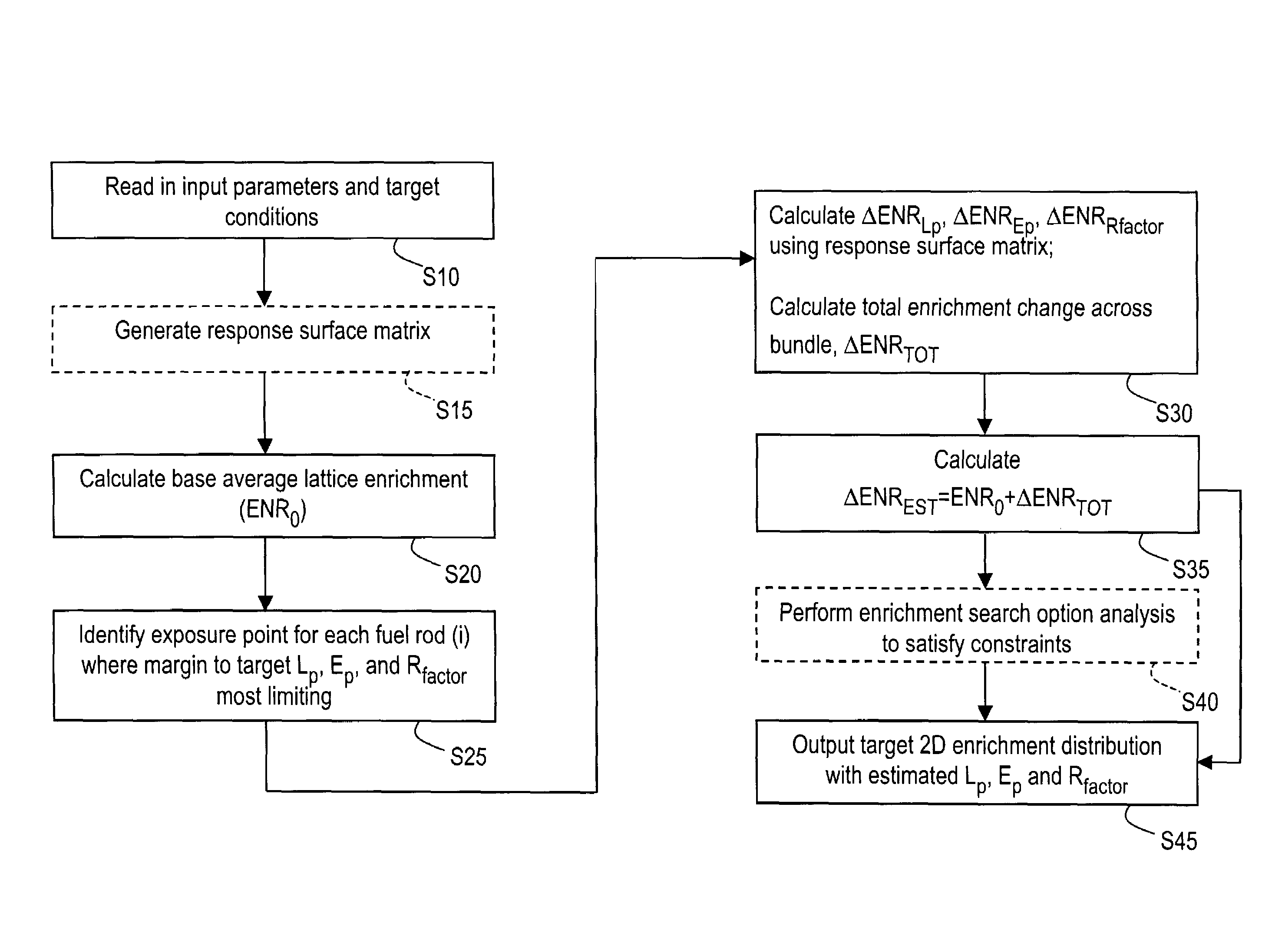
A method and arrangement of determining pin enrichments for a fuel bundle of a nuclear reactor, where a plurality of input parameters and target conditions may be input and enrichment changes, to be made across the fuel bundle, may be calculated using response matrix technology. Fuel bundle pin enrichment data may be output that satisfies the target conditions. The method and arrangement may enable production of fuel bundles having a desired local peaking, exposure peaking and R-factor performance. Consequently, given fuel cycles typically may be loaded and operated such that less fuel may be needed for identical cycle lengths, potentially resulting in improved fuel cycle economics. Additionally, because fuel bundle development may require fewer iterations, there may be a substantial cycle time reduction in the bundle design process, potentially reducing cost and enhancing profitability.

Description

BACKGROUND OF THE INVENTION[0001]1. Field of the Invention[0002]This invention relates generally to nuclear reactors, and more particularly to determining pin enrichments in fuel assemblies of a nuclear reactor.[0003]2. Related Art[0004]A boiling water reactor (BWR) or pressurized water reactor (PWR) typically operates from one to two years before requiring fuel replacement. This period is referred to as a fuel cycle or energy cycle. Upon completion of a cycle, approximately ¼ to ½ (typically about ⅓) of the least reactive fuel in the reactor is discharged to a spent fuel pool. The number of fuel assemblies (e.g., fuel bundles) discharged typically are replaced by an equal number of fresh fuel assemblies (e.g., fresh bundles).[0005]The fresh bundles may vary in bundle average enrichment (the average % of enriched uranium (U235) and poisons (such as gadolinium) across the bundle, determined by the total weight of U235 and gadolinia in the bundle divided by the weight of the bundle, l...

Claims


Application Information

Patent Timeline
IPC IPC(8): G06G7/48G21C19/00G21C7/00G21C9/00G06F17/10G21C3/328G21C17/00G21C19/20
CPCG21C3/328G21D3/001G21C19/205Y02E30/38Y02E30/30Y02E30/00
Inventor RUSSELL, II, WILLIAM EARLJACKSON, ROLAND OTTO
Owner GLOBAL NUCLEAR FUEL -- AMERICAS
Learn More