
Device for recording the pressure and the temperature in an intake manifold of an internal combustion engine

a technology of internal combustion engine and intake manifold, which is applied in the direction of fluid pressure measurement, heat measurement, instruments, etc., can solve the problems of extreme effects that are not able to influence the signal, and the temperature sensor does not provide its own evaluation circuit in the common housing

Active Publication Date: 2009-12-31
ROBERT BOSCH GMBH
View PDF5 Cites 19 Cited by
  • Summary
  • Abstract
  • Description
  • Claims
  • Application Information

AI Technical Summary

Benefits of technology

[0006]One refinement of the present invention provides that the EMC protective circuit be formed of an interference-suppression capacitor. An interference-suppression capacitor represents a simple but extremely effective possibility of ensuring interference suppression of the temperature sensor's signal. It is cost-effective, for one thing, and it is simple to integrate into already present designs, for another thing.
[0011]Still another refinement of the present invention provides that the temperature sensor be electrically connected to the pressure sensor via the EMC protective circuit. This means that at least one electrical terminal of the temperature sensor is connected to at least one electrical terminal of the pressure sensor via the EMC protective circuit. It may be provided, for instance, to connect a ground connection of the temperature sensor to a terminal of the pressure sensor, which represents a positive pole, via the EMC protective circuit. In this way, similarly to the direct connection of the EMC protective circuit to the temperature sensor, interference with the signal of the temperature sensor is able to be prevented. In particular, in this way, sudden voltage drops or increases are filtered out of the signal. In this context, care should be taken that the signal of the temperature sensor via the EMC protective circuit is not able to exert an influence on a signal of the pressure sensor, or vice versa.

Problems solved by technology

This means that the temperature sensor does not provide its own evaluation circuit in the common housing.
Doing it this way, the interference suppression of the temperature sensor takes place in such a way that extreme effects are hardly, or not at all, able to influence the signal of the temperature sensor.

Method used


Image

  • Device for recording the pressure and the temperature in an intake manifold of an internal combustion engine
  • Device for recording the pressure and the temperature in an intake manifold of an internal combustion engine
  • Device for recording the pressure and the temperature in an intake manifold of an internal combustion engine

Examples


Embodiment Construction

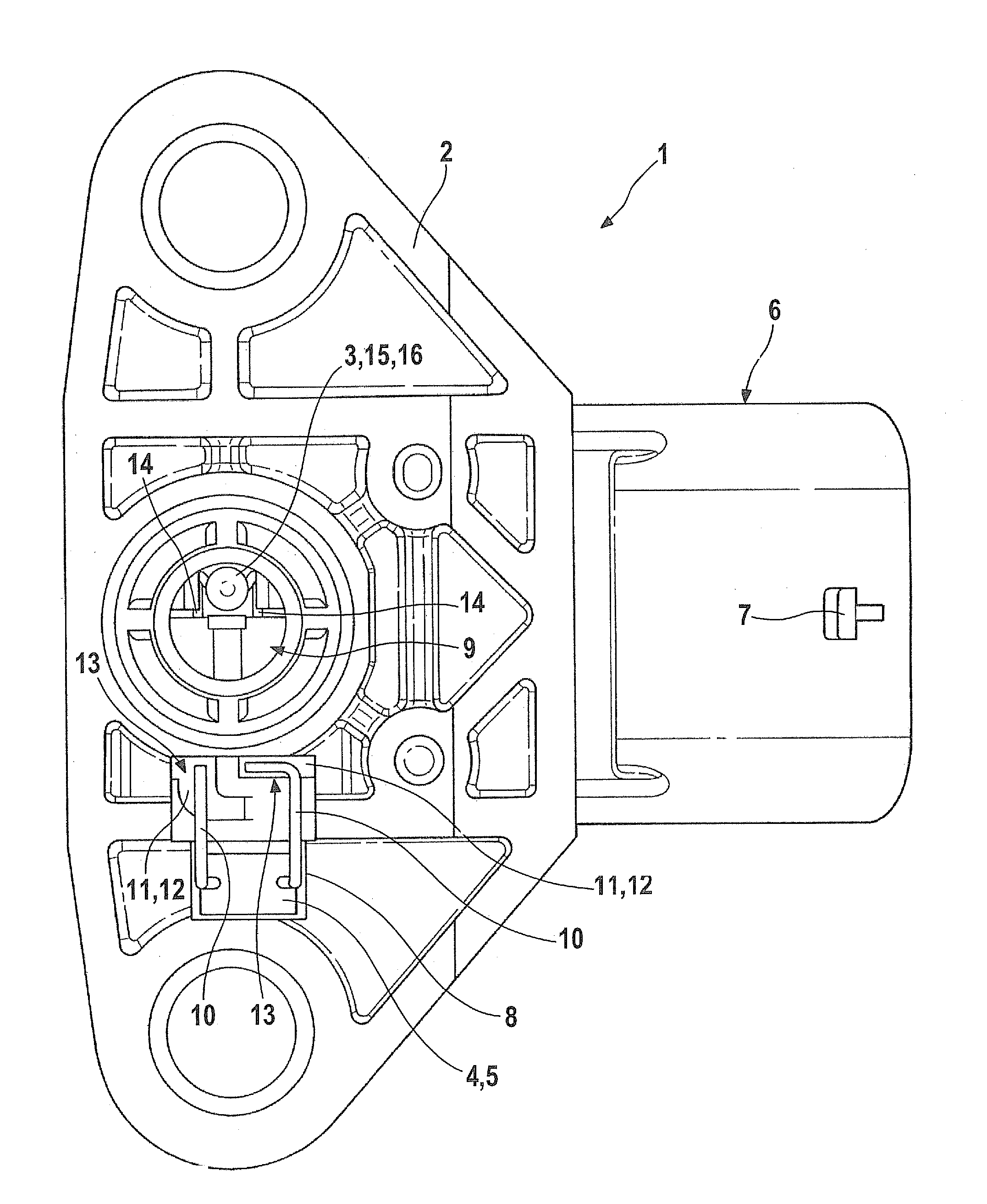
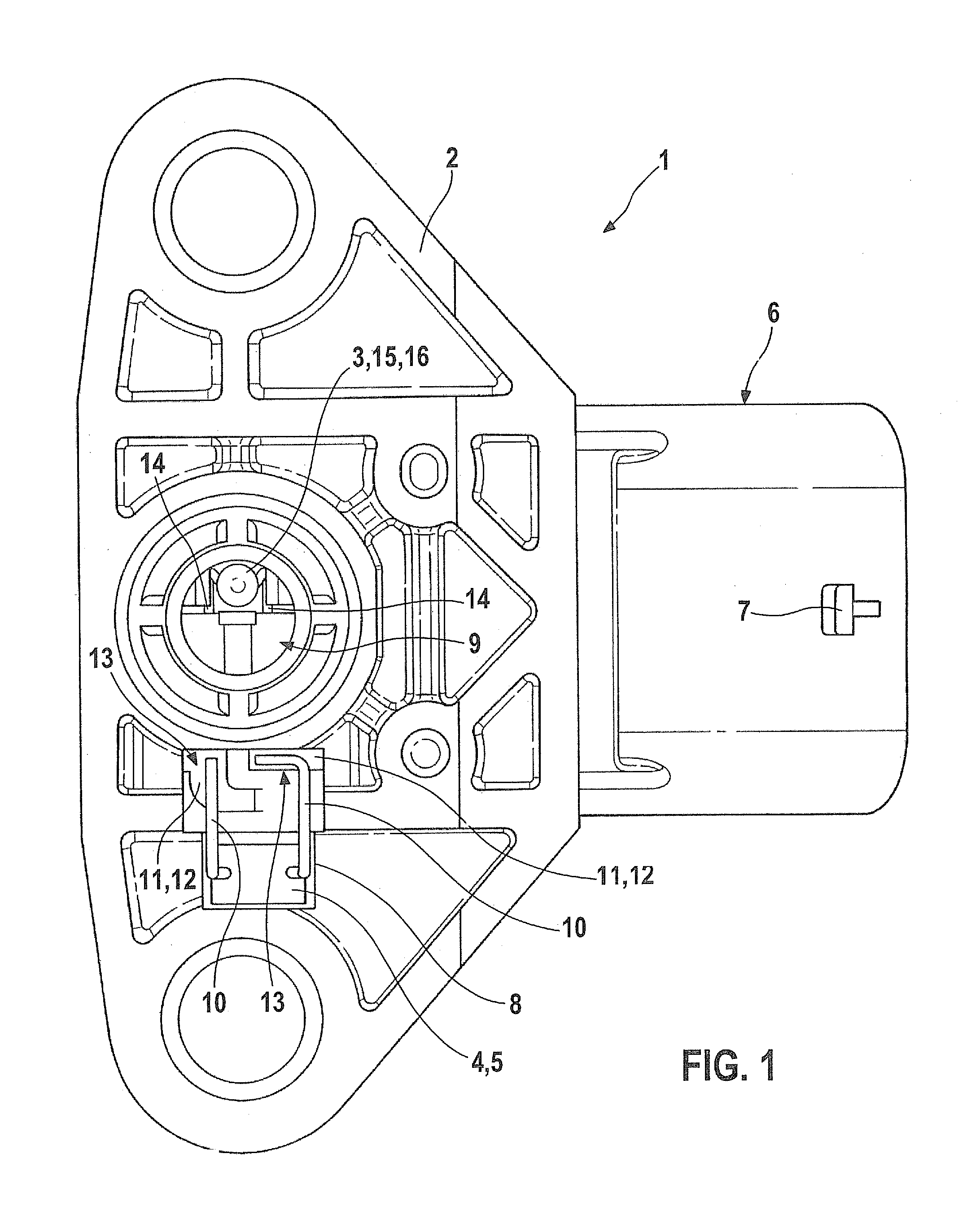
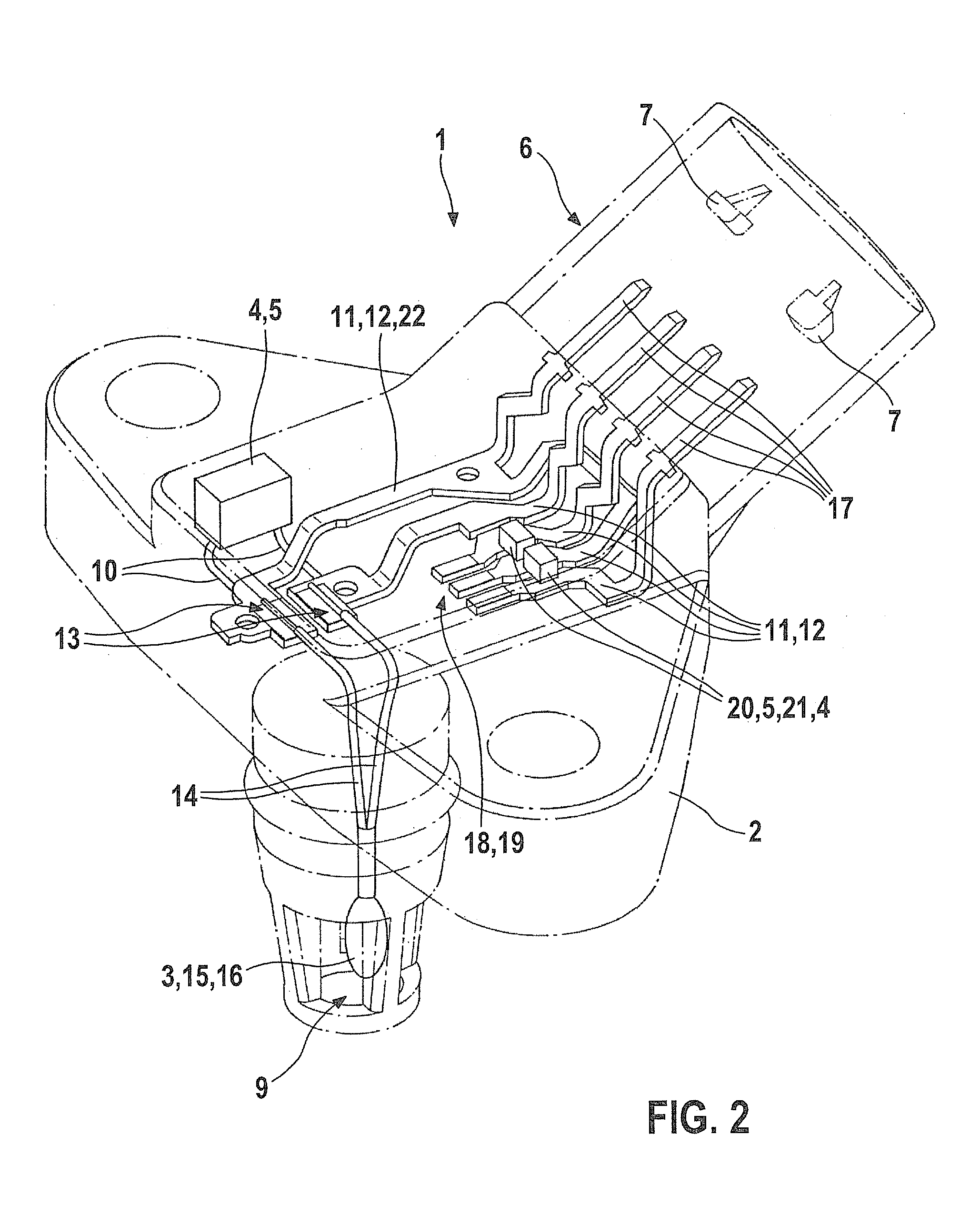
[0020]FIG. 1 shows a device 1 for recording the pressure and the temperature in an intake manifold (not shown) of an internal combustion engine (also not shown). Device 1 has a housing 2 which includes a pressure sensor (not shown), a temperature sensor 3 and an EMC protective circuit 4, that is formed in this case by an interference-suppression capacitor 5. Device 1 is able to be connected to a socket or a coupling (not shown) via a plugging device 6. At least one latching projection 7 takes care of a secure connection between plugging device 6 and the socket or coupling, in this instance. Interference-suppression capacitor 5 is provided in a recess 8 of housing 1, in a first embodiment variant, and is held in it by suitable means. A latching connection or a clamping connection may be provided, for example. Alternatively, interference-suppression capacitor 5 may also be provided with a cover. The latter may be made of a molding compound, using which recess 8 is filled up. Interfere...


PUM


Abstract

A device for recording the pressure and the temperature in an intake manifold of an internal combustion engine, a pressure sensor and a temperature sensor being situated in a common housing, and an evaluation of a signal of the temperature sensor being provided outside the housing. An EMC protective circuit is provided in this context, which is integrated into the housing and / or is situated on the housing, and is electrically connected to the temperature sensor.

Description

FIELD OF THE INVENTION[0001]The present invention relates to a device for recording the pressure and the temperature in an intake manifold of an internal combustion engine, a pressure sensor and a temperature sensor being situated in a common housing, and the evaluation of a signal of the temperature sensor being provided to take place outside the housing.BACKGROUND INFORMATION[0002]Devices are described, for instance, in German Patent No. DE 197 31 420. It describes such a device, in which a temperature sensor and a pressure sensor that is fastened, to the greatest extent in a stress-free manner, on a carrier together with an evaluation circuit, are situated in a common housing. The device described is distinguished by the fact that a very precise pressure measurement is made possible, while its production is very simple. This is achieved by having the housing include at least two chambers that are separate from each other. One of these chambers is connected to the intake manifold ...

Claims


Application Information

Patent Timeline
IPC IPC(8): G01K13/00G01K13/024
CPCG01D11/24G01D21/02G01K1/08G01K13/02G01L19/141G01L19/0084G01L19/0092G01L23/24G01L19/069G01K2205/02
Inventor GEBAUER, JANHABIBI, MASOUDREINHARD, MARKUS
Owner ROBERT BOSCH GMBH
Learn More