
Method and apparatus in various embodiments for hdr implementation in display devices

a display device and display device technology, applied in the field of image display, can solve the problem of not providing all possible design scenarios, and achieve the effect of convenient programming implementation

Inactive Publication Date: 2009-12-31
DOLBY LAB LICENSING CORP
View PDF10 Cites 212 Cited by
  • Summary
  • Abstract
  • Description
  • Claims
  • Application Information

AI Technical Summary

Benefits of technology

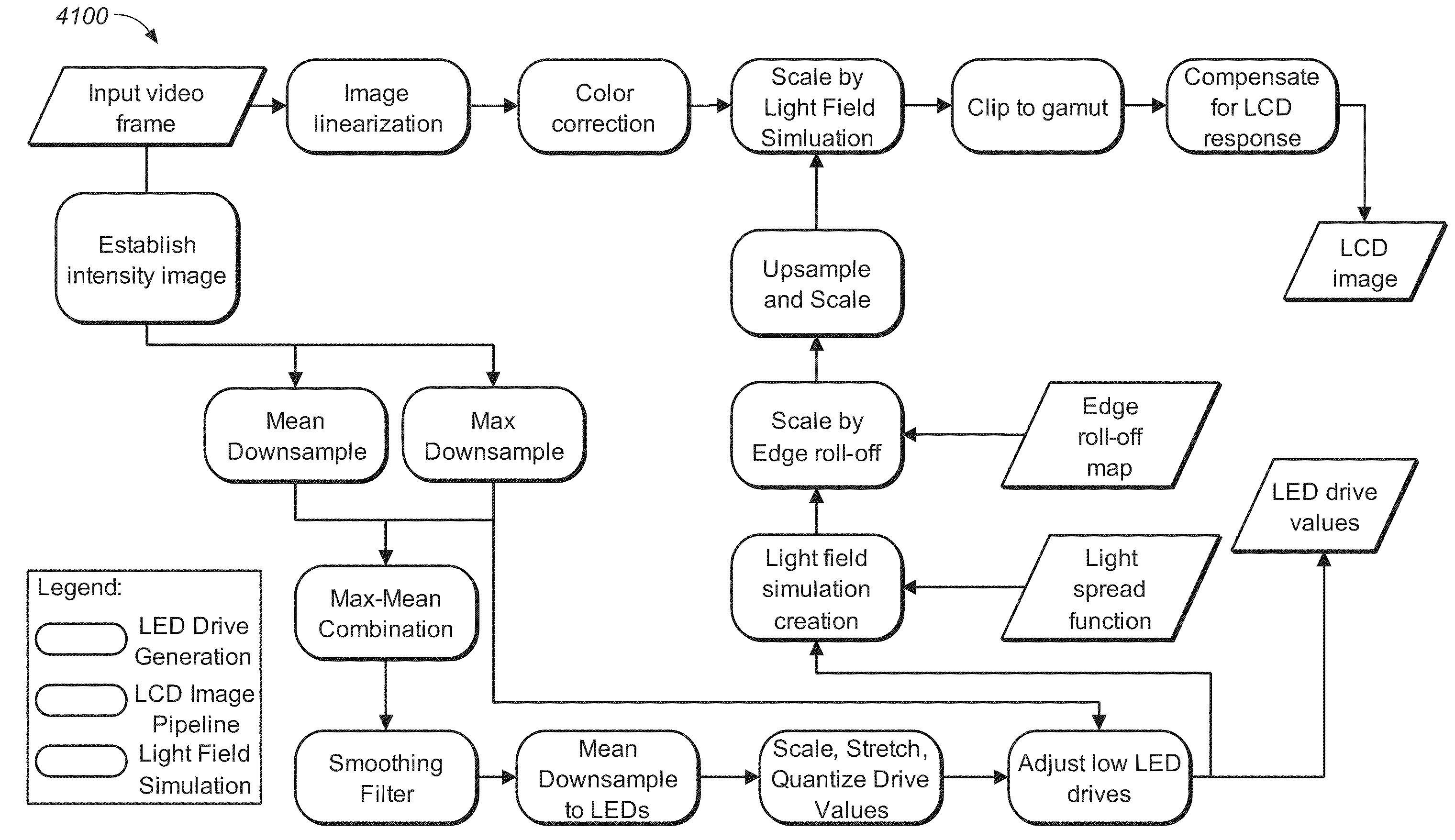
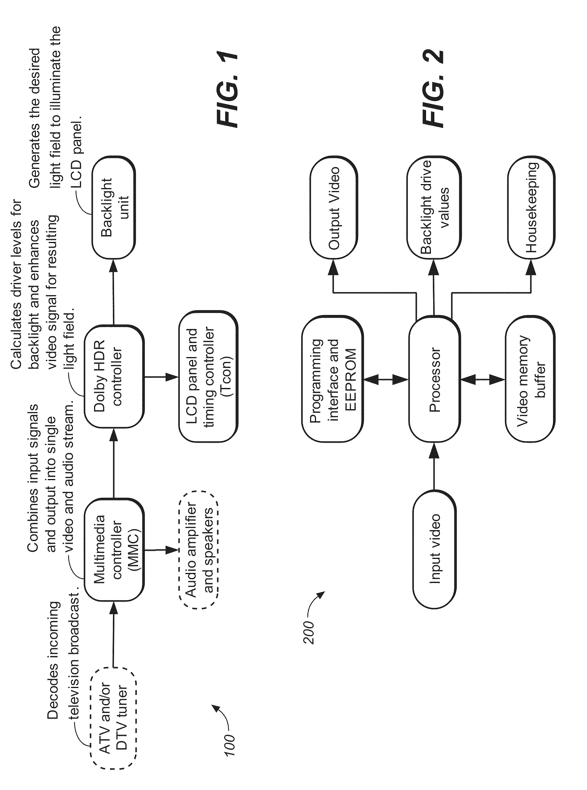
The present invention is about designing and implementing High Dynamic Range (HDR) Displays. It includes various parts, features, and combinations of these parts that make up a device or method for creating quality HDR display results. The invention takes into account various trade-offs and assumes the reader is familiar with LCD and LED technologies. The examples provided in the invention include design recommendations for modulated LED backlights, LCD panel and timing controller, HDR controller, input video, output video, backlight drive values, housekeeping, memory requirements, processing requirements, programming, backlight tiles, backlight control schemes, parallel routing, serial routing, thermal design, electrical design, sensors, mounting, LED drive techniques, constant current, PWM, PCM, PDM, LED drivers, number of outputs, output current, output skew, clock rate, diagnostics, communications, feedback, size and placement, timing and synchronization, video level synchronization, frame level synchronization, timing measurements, power requirements, voltage matching, cables and connectors, shielding, termination, optics, light spread function, LEDs, select LED properties, luminous efficacy, total lumens, light distribution, luminous flux binning, color binning, thermally induced motion artifacts, white point corrections, core algorithm details, LED drive generation, light field simulation, LCD pipeline, and configuration parameters. The invention can be implemented using programming on a computer or networked computers and can be transmitted to a remote device for output or display. The technical effects of the invention include improved quality of HDR display results through various design recommendations and techniques.

Problems solved by technology

This disclosure does not provide all possible design scenarios.

Method used


Image

  • Method and apparatus in various embodiments for hdr implementation in display devices
  • Method and apparatus in various embodiments for hdr implementation in display devices
  • Method and apparatus in various embodiments for hdr implementation in display devices

Examples


Embodiment Construction

[0054]One of the ultimate goals of display systems is to present images that extend to the limit of the human visual system. For example, a Visual Dynamic Range (VDR) pipeline that captures and maintains the full dynamic range of the human visual system from image capture, through post-production and distribution, to display. Conventional display technologies (LCD, CRT, plasma, and so on) have achieved part of that goal by introducing both spatial resolution and refresh rates that are beyond the visual acuity of a human viewer. However, even the highest quality displays available today are incapable of showing the true luminance (brightness) range that we perceive in real life. Every day we encounter light sources in our natural environment that are several orders of magnitude brighter and of higher contrast than in any conventional display. Dolby® HDR technology enhances image quality and realism far beyond that of conventional displays.

[0055]A typical fluorescent light fixture has...


PUM


Abstract

An HDR display is a combination of technologies including, for example, a dual modulation architecture incorporating algorithms for artifact reduction, selection of individual components, and a design process for the display and / or pipeline for preserving the visual dynamic range from capture to display of an image or images. In one embodiment, the dual modulation architecture includes a backlight with an array of RGB LEDs and a combination of a heat sink and thermally conductive vias for maintaining a desired operating temperature.

Description

CROSS-REFERENCE TO RELATED APPLICATIONS[0001]This application claims priority to U.S. Provisional Application No. 61 / 075,443, filed 25 Jun. 2008 and 61 / 105,642, filed 15 Oct. 2008, which is hereby incorporated by reference in its entirety.COPYRIGHT NOTICE[0002]A portion of the disclosure of this patent document contains material which is subject to copyright protection. The copyright owner has no objection to the facsimile reproduction by anyone of the patent document or the patent disclosure, as it appears in the Patent and Trademark Office patent file or records, but otherwise reserves all copyright rights whatsoever.BACKGROUND OF THE INVENTION[0003]1. Field of Invention[0004]The present invention relates to image display.[0005]2. Discussion of Background[0006]A goal of display systems is to present images that extend to the limit of the human visual system. Conventional display technologies (LCD, CRT, and plasma, for example) have achieved part of that goal by introducing both sp...

Claims


Application Information

Patent Timeline
Patent Type & Authority Applications(United States)
IPC IPC(8): G09G5/10G09G3/36
CPCG09G3/2014G09G3/2018G09G3/3413G09G5/10G09G2330/045G09G3/006G09G3/3426
Inventor ATKINS, ROBIN
Owner DOLBY LAB LICENSING CORP
Learn More