
Antenna assembly having multiple antenna elements with hemispherical coverage

a technology of antenna elements and antenna assemblies, applied in the direction of individual energised antenna arrays, resonant antennas, radiating element structural forms, etc., can solve the problems of antenna not receiving, potential sources of error, and limited bandwidth

Active Publication Date: 2009-12-31
TYCO ELECTRONICS LOGISTICS AG (CH)
View PDF11 Cites 19 Cited by
  • Summary
  • Abstract
  • Description
  • Claims
  • Application Information

AI Technical Summary

Benefits of technology

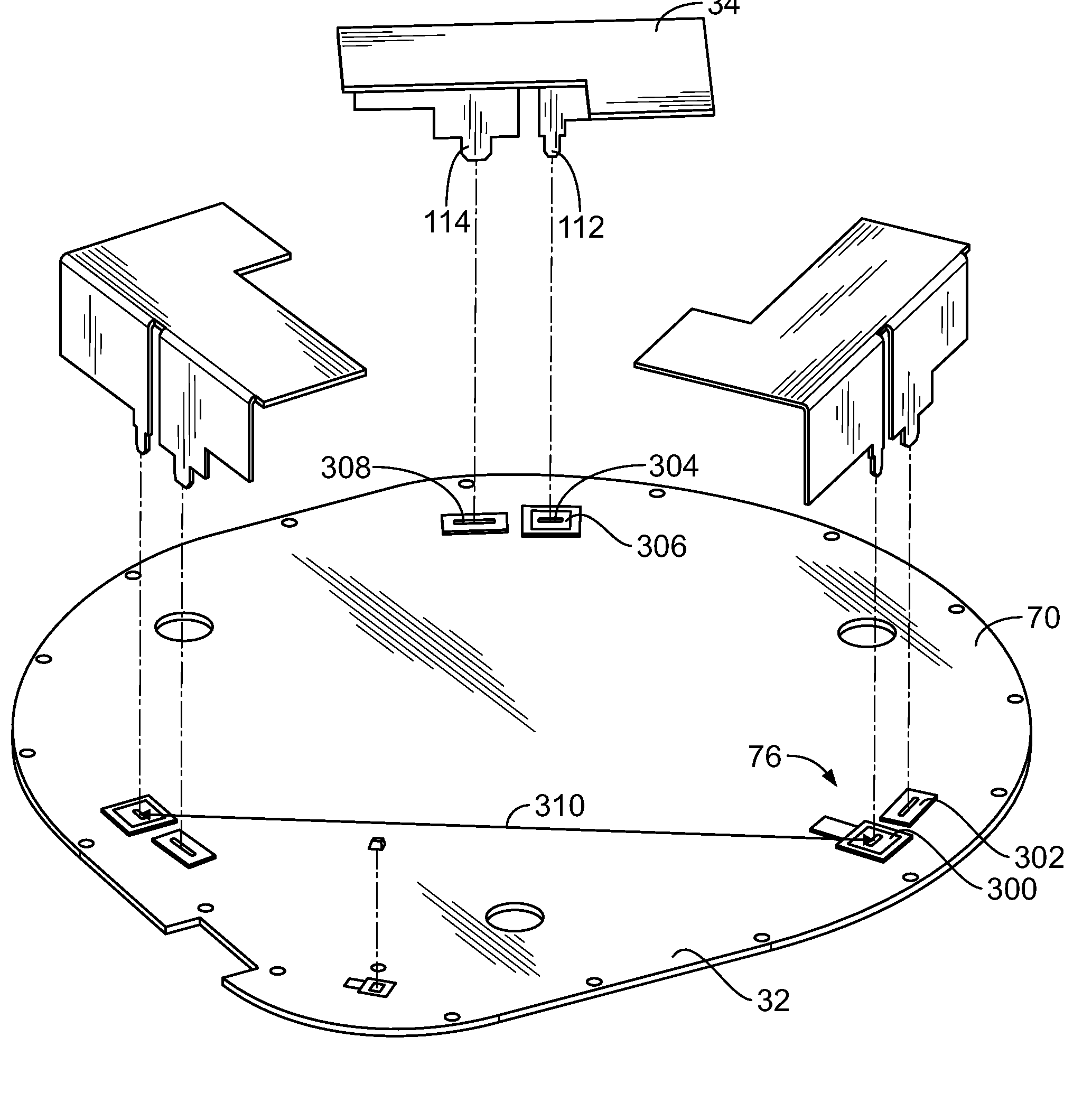
[0007]Optionally, each antenna element may be identically formed. The first portion may extend perpendicular to the ground plane and the second portion may extend perpendicular to the first portion. The feed finger and the ground finger may be separated from one another by a slot that has a predetermined length and width to control the impedance of the antenna element. Optionally, three antenna elements may be provided such that each antenna element is positioned equidistant from each other antenna element.

Problems solved by technology

Typically, the antennas are designed to operate in a relatively narrow frequency range and thus have a limited bandwidth.
One limitation of these antenna is that the antenna does not receive in the direction in which the rod points.
For instance, in wireless LAN data transfer operations, loss of signal strength, interruptions in data transfer, and the deleterious effects of signal interference all present potential sources of error and problems with known antennas during data transfer.
These problems are exaggerated with antennas that operate in wider frequency ranges.

Method used


Image

  • Antenna assembly having multiple antenna elements with hemispherical coverage
  • Antenna assembly having multiple antenna elements with hemispherical coverage
  • Antenna assembly having multiple antenna elements with hemispherical coverage

Examples


Embodiment Construction

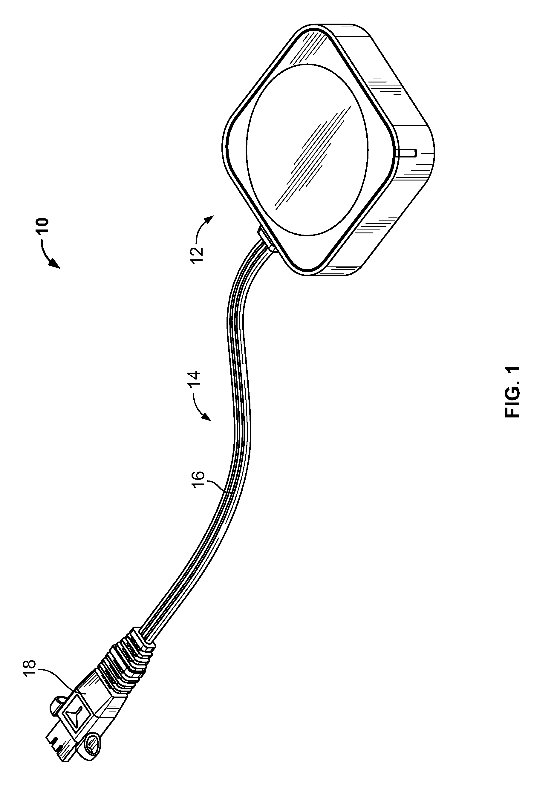
[0020]FIG. 1 is a top perspective view of an antenna assembly 10 formed in accordance with an exemplary embodiment. The antenna assembly 10 includes an antenna housing 12 and a cable assembly 14 extending from the antenna housing 12. The cable assembly 14 includes a cable 16 and a connector 18 at an end of the cable 16. The connector 18 is configured to be connected to a mating connector (not shown) of a device (not shown). In an exemplary embodiment, the device is a wireless communication device, such as a computer, game console, cell phone, MP3 player, PDA, and the like. The device uses the antenna assembly 10 to enable wireless access to applications, data, media and / or streams. In an exemplary embodiment, the antenna assembly 10 is a high isolation multiple in, multiple out (MIMO) antenna assembly.

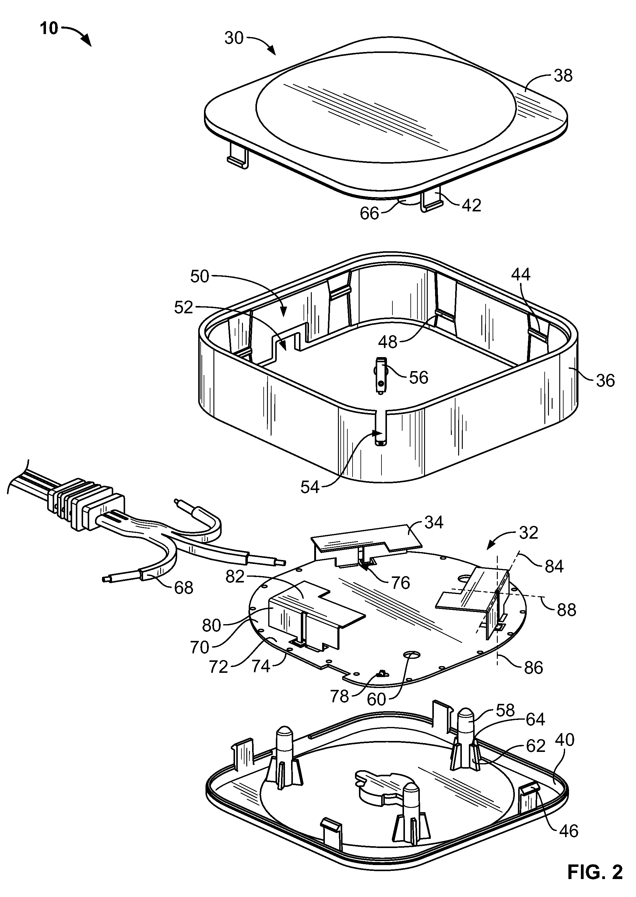
[0021]FIG. 2 is an exploded view of the antenna assembly 10. The antenna assembly 10 includes a housing 30, a circuit board assembly 32 that is held within the housing 30, and multiple...


PUM


Abstract

An antenna assembly includes a cable assembly having at least one wire and a circuit board assembly having a ground plane and a plurality of mounting locations. The wire(s) is electrically connected to corresponding mounting locations. A plurality of antenna elements are mounted to the circuit board at corresponding mounting locations. Each antenna element has a feed finger and a ground finger, where the ground finger is electrically connected to the ground plane and the feed finger is electrically connected to the corresponding wire. Each antenna element has a first portion extending from the circuit board along a first plane and a second portion extending from the first portion along a second plane that is transverse to the first plane. Each antenna element provides hemispherical coverage and wide frequency bandwidth.

Description

BACKGROUND OF THE INVENTION[0001]The subject matter herein relates generally to antenna assemblies, and more particularly, to antenna assemblies having multiple antenna elements with hemispherical coverage.[0002]Wireless communication devices are in wide use today, particularly due to the convenience of enabling wireless access to applications and data. Wireless communication devices typically utilize antenna assemblies to establish a wireless connection with other devices. Typical wireless communication devices include computers, game consoles, cell phones, MP3 players, PDA's and the like, that are coupled to a network such as a wireless local area network (LAN). The LANs are used in the wireless transmission and reception of digitally-formatted data using transceivers operating at least one frequency range, such as 2.4-2.5 GHz., 5.2-5.8 GHz., and others. Antennas are required for the transceivers operating over these frequency bands. Typically, the antennas are designed to operate...

Claims


Application Information

Patent Timeline
Patent Type & Authority Applications(United States)
IPC IPC(8): H01Q21/00H01Q9/04H01Q5/10
CPCH01Q21/20H01Q9/0421
Inventor BISHOP, BRUCE FOSTERCARDENAS, LUIS
Owner TYCO ELECTRONICS LOGISTICS AG (CH)
Learn More