Regulation of electrical generator output

a technology for electrical generators and regulators, applied in the direction of electric generator control, process and machine control, instruments, etc., can solve the problems of slow transient response, low reliability, high cost, etc., and achieve the effect of facilitating the generation of a stable dc level, reducing complexity and prone to problems, and facilitating tuning

Inactive Publication Date: 2016-07-21
BDR THERMEA GRP
View PDF19 Cites 7 Cited by
  • Summary
  • Abstract
  • Description
  • Claims
  • Application Information

AI Technical Summary

Benefits of technology

[0024]The first and second sub-controllers are typically of different types. The first sub-controller is preferably a feedforward controller and more preferably comprises a clamp controller. Additionally (or alternatively), the second sub-controller may comprise an error compensator, as is known for a typical Single Input Single Output (SISO) control strategy. A range of types of error compensator can be used. The preferred type is a form of Proportional-Integral-Derivative (PID) controller. This may be a Proportional controller or a Proportional-Integral (PI) controller in preferred embodiments. This may be easier to tune and it may work well when the plant (that is, the generator) characteristic is unknown. Other types of error compensator may include lead and lag compensators, as long as the closed system response is stable.
[0025]Advantageously, the second sub-controller uses a DC level as a reference (particularly when the second sub-controller comprises a PID-type of controller). This assists in making the regulator less complex and prone to problems, because it is not necessary to synchronise the reference voltage with the generator output when a DC level is used. Moreover, it is easier to generate a stable DC level. Additionally or alternatively, the second sub-controller beneficially compares a time-averaged value for the at least one characteristic of the electrical output with a reference. This provides a simple and efficient slow-response sub-controller. Moreover, the controller can also cope with non-sinusoidal waveforms as well as sinusoidal ones.

Problems solved by technology

These present several drawbacks such as slow transient response, low reliability and higher cost.
An impedance sensed by the alternator that is too high or too low could result in over-voltage, waveform distortion, and in extreme cases (such as an open or short circuit) physical damage of the generator engine.
However, there is often no inherent protection for the engine or alternator if they are used to provide electrical energy to connected appliances when disconnected from electrical mains, as in the case of a grid power blackout.
When appliances are first connected to the generator these loads may demand “inrush” currents that are greatly in excess of those normally provided by the alternator.
Inductive loads could also require high levels of current for short periods of time.
However, it requires a significant amount of regulation-specific processing.

Method used


Image

  • Regulation of electrical generator output
  • Regulation of electrical generator output
  • Regulation of electrical generator output

Examples


Embodiment Construction

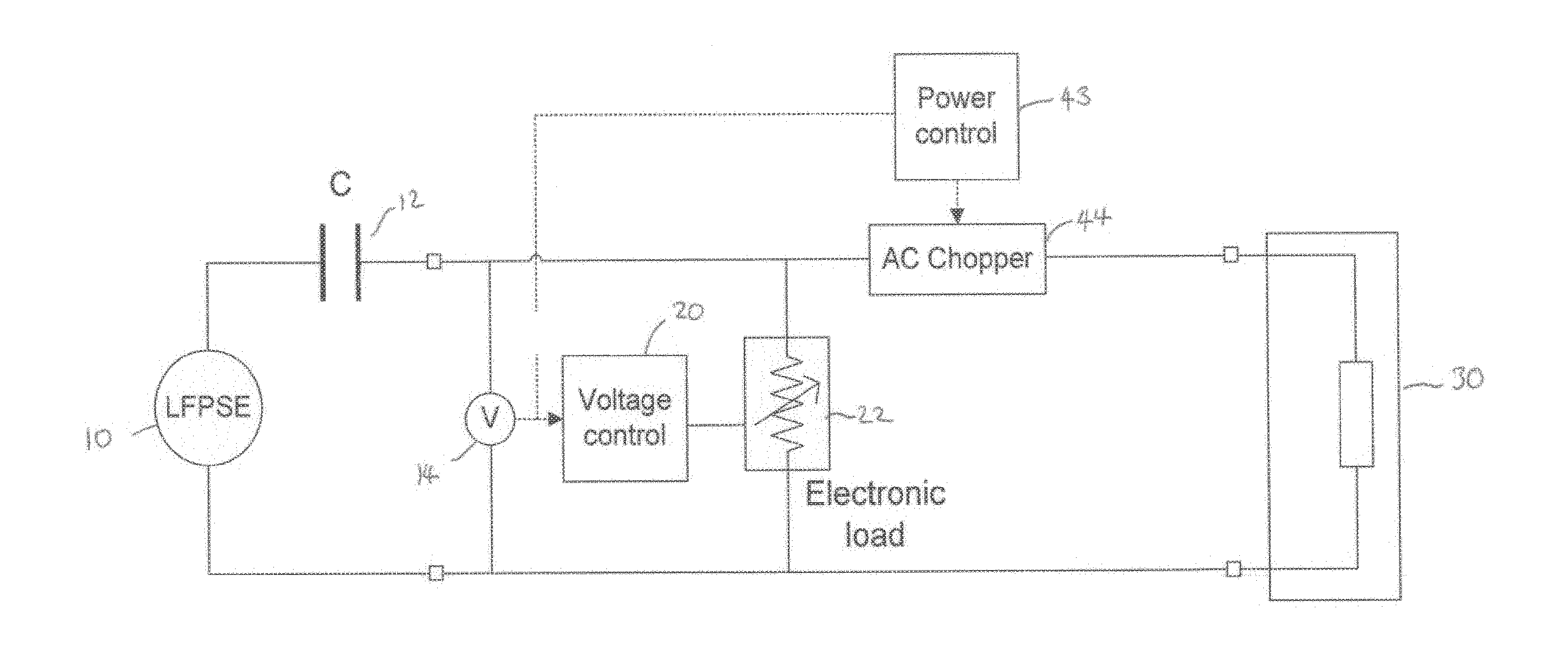
[0057]Referring first to FIG. 2E, there is shown an equivalent circuit for a regulator technology in accordance with the invention. Some of the components of this circuit are the same as FIG. 2D and these are indicated by identical reference numerals. A power control block 43 uses the voltage measured by voltmeter 14 to generate a control signal for the AC chopper 44. Thus, a current meter and a second voltmeter are not needed. This circuit is intended to form a bridge between the alternator of a DCHP unit (of which the LFPSE 10 forms a part), an electrical grid and also local electrical appliances to ensure that the signal produced by the alternator is suitable for injection into the grid, supply to the connected appliances or both.

Control Approach

[0058]Referring next to FIG. 4A, there is shown a schematic diagram for an approach to generating an error signal for regulation of the output voltage for a generator based on a FPSE / LA. This is embodied as a voltage control block 100. Wh...


PUM


Abstract

To regulate the electrical output of a generator, a signal is received indicative of at least one characteristic of the electrical output. A first, relatively fast-response sub-controller is configured to provide a first control signal on the basis of the at least one characteristic and a second, relatively slow-response sub-controller is configured to provide a second control signal on the basis of the at least one characteristic. An output provides a combined control signal to adjust the electrical output based on the first and second control signals.

Description

TECHNICAL FIELD OF THE INVENTION[0001]The invention concerns a regulator for the electrical output of a generator, in particular wherein the generator comprises a Stirling engine (especially a linear free piston Stirling engine with linear alternator) and a method of regulating the electrical output of such a generator.BACKGROUND TO THE INVENTION[0002]The application of a Free Piston Stirling Engine (FPSE) with a Linear Alternator (LA) to generate electricity in Domestic Combined Heat and Power (DCHP) units that provide hot water and central heating in a domestic environment is well known. Referring to FIG. 1, there is shown a typical power characteristic curve of a FPSE / LA, which is similar to that shown in U.S. Pat. No. 4,642,547. The power output of a FPSE / LA therefore depends on the head temperature. It may be understood that the amplitude and polarity of magnetic flux created by the permanent magnets changes when the power piston moves relative to the armature winding (stator)....

Claims


Application Information

Patent Timeline
Patent Type & Authority Applications(United States)
IPC IPC(8): H02P9/04
CPCH02P9/04H02P9/48F02D29/06F02G1/045G05F1/565H02P9/30
Inventor GREEN, ADAM HENRYTORRES-PEREZ, ANGELMCARDLE, MICHEAL GERARD
Owner BDR THERMEA GRP
Why Eureka
Try Eureka