[0013]Therefore, in the photodetector according to the aspect of the invention, it is possible to output the received
photocurrent in which not only influences of light from the backlight and temperature characteristics of photodiodes themselves but also an influence of a near-
infrared light component (specifically, a near-
infrared light component of ambient light) not sensed by human eyes is eliminated. In other words, also in a case where each of the first and second light receiving elements has sensitivity to the near-
infrared light component, the photodetector according to the aspect of the invention can output the received
photocurrent in which the influence of the near-infrared light component not sensed by human eyes is eliminated. That is, also in the case where each of the first and second light receiving elements has a
spectral sensitivity effective in the relative luminous
wavelength band of human eyes but the
spectral sensitivity characteristic of each of the first and second light receiving elements is different from the relative
luminosity characteristic of human eyes, the
spectral sensitivity characteristic as the whole photodetector can be brought relatively close to the relative
luminosity characteristic of human eyes. For example, in a situation where it is sensed that the surrounding environment (that is, ambient light) is ‘dark’ by human eyes, a received
photocurrent indicating that the ambient light is relatively dark can be output. In addition, in a situation where it is sensed that the surrounding environment (that is, ambient light) is relatively ‘bright’ by human eyes, a received photocurrent indicating that the ambient light is relatively bright can be output. Therefore, in the photodetector according to the aspect of the invention, the
light intensity of surrounding ambient light can be suitably detected.
[0014]In addition, since the red color filter is used, the configuration of the above-described photodetector can be realized without adding a special manufacturing process or using a special material. As a result, the above-described photodetector can be realized relatively easily or cheaply.
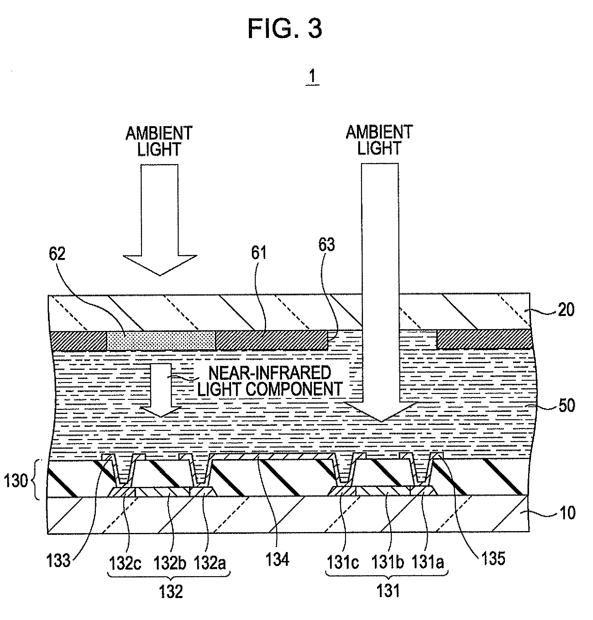
[0017]In this case, ambient light transmitted through the first green color filter and light, which is not transmitted (or which is transmitted) through at least one of the red color filter and the first green color filter, other than the ambient light are incident on the
first light receiving element. Accordingly, a ‘received photocurrent generated when receiving a visible light component of ambient light (in particular, a visible light component of ambient light corresponding to the relative
luminosity characteristic of human eyes which is obtained when the ambient light is transmitted through the green color filter)’, which is a difference between a light receiving result in the
first light receiving element and a light receiving result in the second light receiving element, is output to the detection circuit to be described later. For this reason, also in the case where each of the first and second light receiving elements has a spectral sensitivity effective in the relative luminous
wavelength band of human eyes but the spectral sensitivity characteristic of each of the first and second light receiving elements is different from the relative luminosity characteristic of human eyes, the spectral sensitivity characteristic as the whole photodetector (in particular, the spectral sensitivity characteristic of the whole photodetector with respect to the ambient light) can be brought relatively close to the relative luminosity characteristic of human eyes. As a result, the
light intensity of surrounding ambient light can be detected more suitably.
[0018]In addition, the first green color filter is a filter that mainly transmits a
green light component. For example, a green color filter used to realize color display in a typical electro-optical device may be used as the above first green color filter. Thus, the configuration of the above-described photodetector can be realized without adding a special manufacturing process or using a special material. As a result, the above-described photodetector can be realized relatively easily or cheaply.
[0021]In addition, the second green color filter is a filter that mainly transmits a
green light component. For example, a green color filter used to realize color display in a typical electro-optical device may be used as the above second green color filter. Thus, the configuration of the above-described photodetector can be realized without adding a special manufacturing process or using a special material. As a result, the above-described photodetector can be realized relatively easily or cheaply.
[0027]The photodetector according to the aspect of the invention can output a received photocurrent in which an influence of a near-infrared light component not sensed by human eyes is eliminated. In other words, also in a case where each of the first and second light receiving elements has sensitivity to the near-infrared light component, the photodetector according to the aspect of the invention can output the received photocurrent in which the influence of the near-infrared light component not sensed by human eyes is eliminated. That is, also in the case where each of the first and second light receiving elements has a spectral sensitivity effective in the relative luminous
wavelength band of human eyes but the spectral sensitivity characteristic of each of the first and second light receiving elements is different from the relative luminosity characteristic of human eyes, the spectral sensitivity characteristic as the whole photodetector can be brought relatively close to the relative luminosity characteristic of human eyes. For example, in a situation where it is sensed that the surrounding environment (that is, ambient light) is ‘dark’ by human eyes, a received photocurrent indicating that the ambient light is relatively dark can be output. In addition, in a situation where it is sensed that the surrounding environment (that is, ambient light) is relatively ‘bright’ by human eyes, a received photocurrent indicating that the ambient light is relatively bright can be output. Therefore, in the photodetector according to the aspect of the invention, the
light intensity of surrounding ambient light can be suitably detected.
