
Releasing slips for oil well tool

a technology for oil wells and tools, applied in the direction of fluid removal, sealing/packing, borehole/well accessories, etc., can solve the problems of slipping into the casing wall while holding down the tool, affecting and the slipping can be extremely difficult to release, so as to achieve the effect of improving the service life of the releasing slip

Inactive Publication Date: 2009-12-31
KLINE ALBERT E +1
View PDF26 Cites 2 Cited by
  • Summary
  • Abstract
  • Description
  • Claims
  • Application Information

AI Technical Summary

Benefits of technology

[0009]This present invention replaces the releasing slips with a part or parts that have no biting effect on the casing. In one embodiment, the surface of the releasing slip of the present invention is entirely smooth. When pulled upwards, the releasing slips of the present invention move up much more easily, allowing the tool to move laterally, thereby partially unloading the remaining slips, and thus allowing the remaining slips to more easily release. The releasing slips in this case are, in practice, used as a wedge, which allow the remaining slips to function normally. The releasing slips of the invention are not required to provide biting capability for the hold down tool to perform its function. The releasing slips of the invention allow the tool to release much more easily, especially in severe applications.
[0010]A second embodiment of the present invention utilizes one or more hardened carbide pieces or other suitable material on the contacting face of the releasing slip of the invention. The smooth surface of the hardened piece or pieces are preferably configured such that the piece or pieces lay flat against a wall, thereby providing greatly reduced resistance to release. The carbide pieces are harder than any standard grade of casing, which greatly reduces wear on the part.
[0012]There are several advantages of the present invention. Most importantly, a tool utilizing the inventive slips significantly reduces the problems described above with respect to removal of the tool. The monetary benefit associated with the tool includes the relatively smaller benefits associated with improved service life of the releasing slips and also the substantially larger benefits associated with avoiding an inability to release the tool.

Problems solved by technology

One difficulty associated with the use of conventional slips or gripping members is that the slips that are engaged with the wellbore can be extremely difficult to release when it is desired to release the tool.
One drawback of hold down tools utilizing prior art designs is that, when engaged, the slips bite into the casing wall while the hold down tool is performing its functions.
Therefore, during release, even the releasing slips provide resistance, which causes problems including that the biting surfaces of the releasing slips become worn fairly quickly, requiring their replacement.
An additional difficulty is that during higher pressure operations, the releasing slips can provide sufficient resistance that release becomes difficult and may also cause other problems.
These problems may include overstressing the pulling unit topside, parting of the tubing that is used to transfer the tension from the pulling unit to the tool, rupture or permanent deformation of the mounting device for the slips, and ultimately, an inability to remove the tool at all.

Method used


Image

  • Releasing slips for oil well tool
  • Releasing slips for oil well tool
  • Releasing slips for oil well tool

Examples


Embodiment Construction

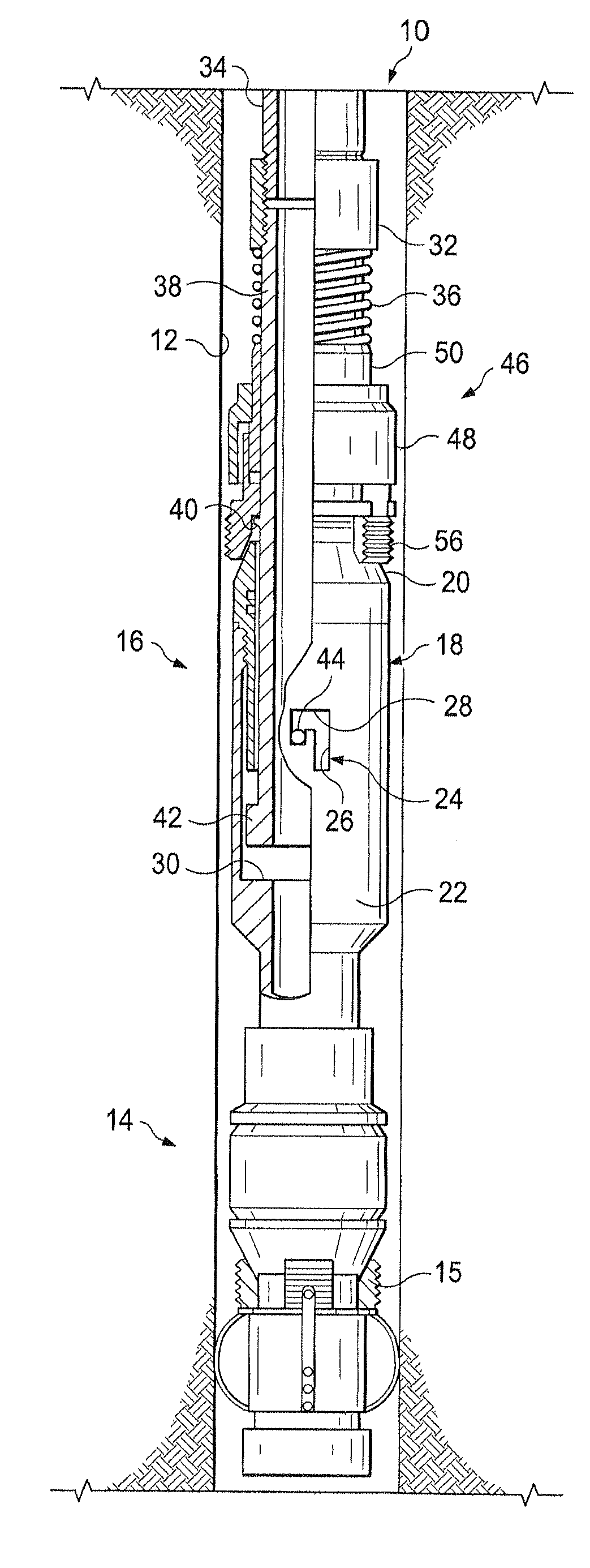
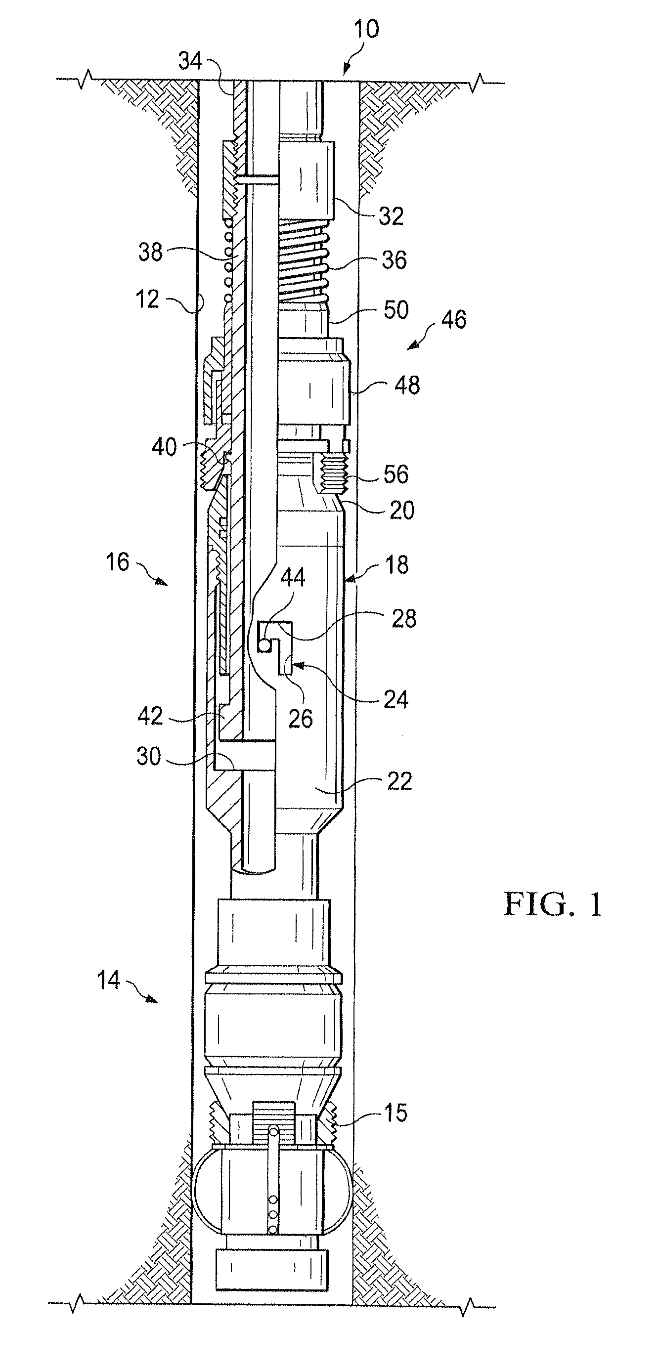
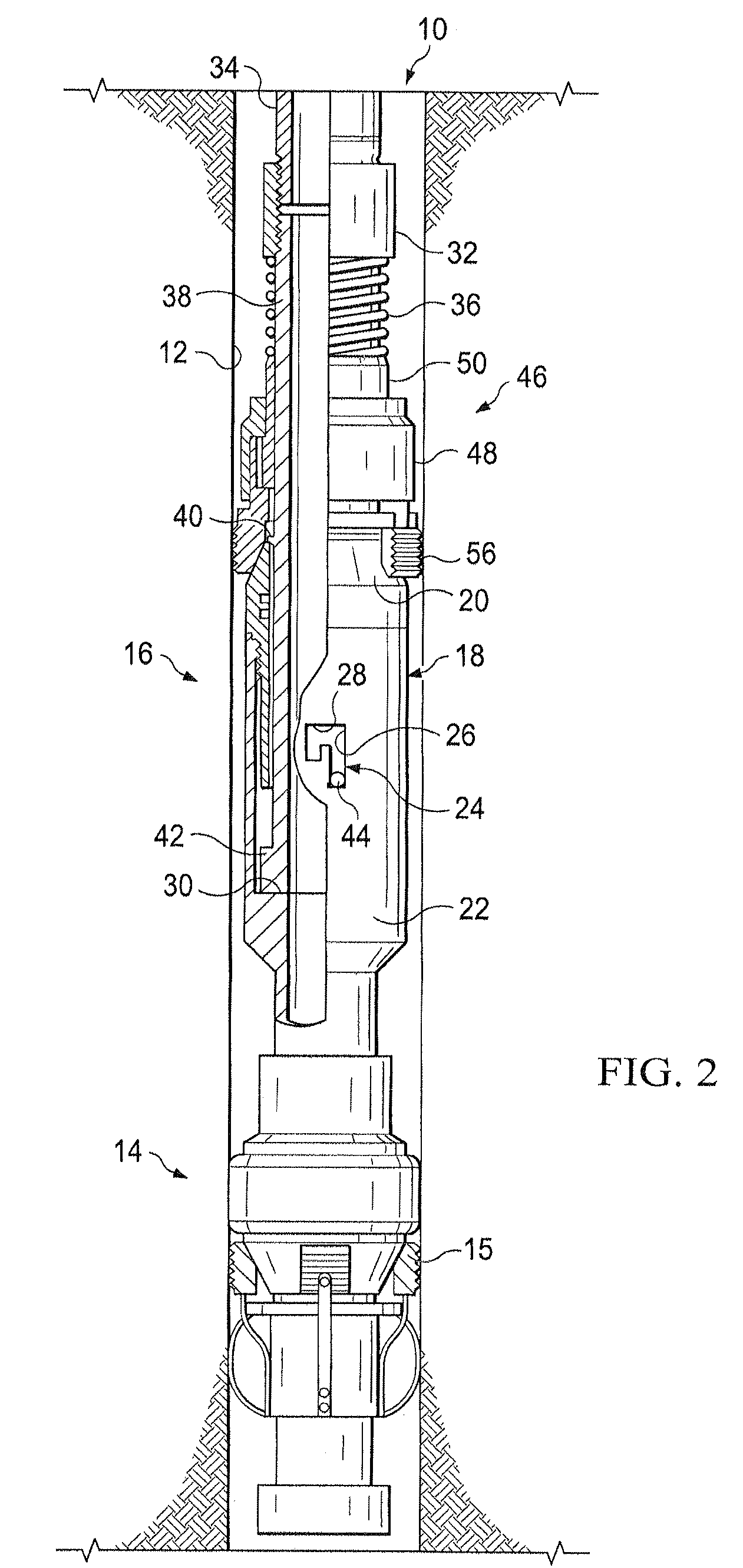
[0022]Referring first primarily to FIGS. 1 and 2, shown is well bore 10 having a wall 12. A packer 14 is shown lowered into well bore 10. Packer 14 includes an expansible element such as packer slips 15 for selectively engaging wall 12. A hold down tool 16 is connected to packer 14. Hold down tool 16 includes a cone assembly 18. Cone assembly 18 has an upwardly facing cone 20 and an outer casing 22. Outer casing 22 defines a j-slot 24 having a long vertical section 26 and a short horizontal section 28. Cone assembly 18 further defines an internal abutment 30.

[0023]A coupling member 32 is attached to an upper end of hold down tool 16. A tubing string 34 is connected to coupling member 32 for supporting hold down tool 16 and packer 14 within well bore 10.

[0024]A spring 36 is located above hold down tool 16. Spring 36 has an upper end in abutment with coupling member 32. A cylindrical mandrel 38 extends downwardly inside cone assembly 18. Mandrel 38 defines a protuberance 40 and has a ...


PUM


Abstract

Releasing slips for use with a downhole tool, a tool for deploying downhole in a well utilizing the releasing slips and a well in which a downhole tool is deployed utilizing the releasing slips of the invention is described herein. The tool has a plurality of slips for selective engagement with a wall of a wellbore. The slips include releasing slips and biting slips. The releasing slips have a low friction surface, e.g., a substantially smooth surface for engaging the wall of the wellbore. The smooth wall engaging face of the releasing slips facilitate easy release of the slips, thereby facilitating easy removal of the downhole tool. The slips may include a plurality of hardened members that protrude from the wall engaging face of the releasing slips to reduce wear on the face of the releasing slip.

Description

FIELD OF THE INVENTION[0001]The invention relates to an improved releasing slip for use with a hold down tool / bridge plug / packer for lowering into a wellbore. In particular, the releasing slip of the invention has a low friction face to facilitate ease of release.BACKGROUND OF THE INVENTION[0002]A production packer is a standard component of completion hardware in oil and gas wells. Production packers are used to provide a seal between the outside of production tubing and the inside of a casing, liner, or wellbore wall. When recovering oil and gas from a well, in many geological formations it is necessary to isolate the zone containing the oil and gas producing formation from the remainder of the underground structure so as to prevent contamination of the oil and gas producing zone from salt water or other undesirable contaminants.[0003]Packers may be lowered into the well and expanded to isolate the oil and gas producing zone. Packers may be placed above and below the producing zon...

Claims


Application Information

Patent Timeline
Patent Type & Authority Applications(United States)
IPC IPC(8): E21B23/06E21B33/129
CPCE21B33/134E21B33/129
Inventor KLINE, ALBERT E.PASCHEN, GEORGE W.
Owner KLINE ALBERT E
Learn More