
Overcoming LDPC trapping sets by decoder reset

a decoder and reset technology, applied in the field of overcoming ldpc trapping sets by decoder reset, can solve the problems of affecting the effect, the error rate of the required decoder output block, and the proportionality of the memory complexity of the decoding hardware to the code length

Inactive Publication Date: 2009-12-24
RAMOT AT TEL AVIV UNIV LTD
View PDF100 Cites 59 Cited by
  • Summary
  • Abstract
  • Description
  • Claims
  • Application Information

AI Technical Summary

Benefits of technology

[0035]It is well known that the error correction capability and the error floor of an iterative coding system improve as the code length increases (this is true for any ECC system, but especially for iterative coding systems, in which the error correction capability is rather poor at short code lengths).
[0037]Therefore, presented herein are methods for implementing extremely long LDPC codes that provide very low error floor and near optimal error correction capability, using low complexity decoding hardware.
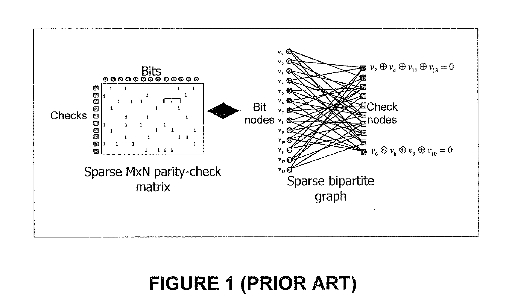
[0038]While properly designed LDPC codes are very powerful, and can correct a large number of errors in a code word, a phenomenon known as “trapping sets” may cause the decoder to fail, and increase the error floor of the code, even though the number of incorrect bits may be very small and may be confined to certain regions in the graph. Trapping sets are not well defined for general LDPC codes, but have been described as: “These are sets with a relatively small number of variable nodes such that the induced sub-graph has only a small number of odd degree check nodes.”

Problems solved by technology

This effect is problematic, especially in storage systems, where the required decoder output block error rate should be very small (˜10−10).
However, in conventional implementations of iterative coding systems, the memory complexity of the decoding hardware is proportional to the code length; hence using long codes incurs high complexity, even in the most efficient implementations known (e.g. serially scheduled decoders).

Method used


Image

  • Overcoming LDPC trapping sets by decoder reset
  • Overcoming LDPC trapping sets by decoder reset
  • Overcoming LDPC trapping sets by decoder reset

Examples


Embodiment Construction

[0090]The principles and operation of low-complexity LPDC decoding and of LPDC decoding that overcomes non-convergence due to trapping sets may be better understood with reference to the drawings and the accompanying description.

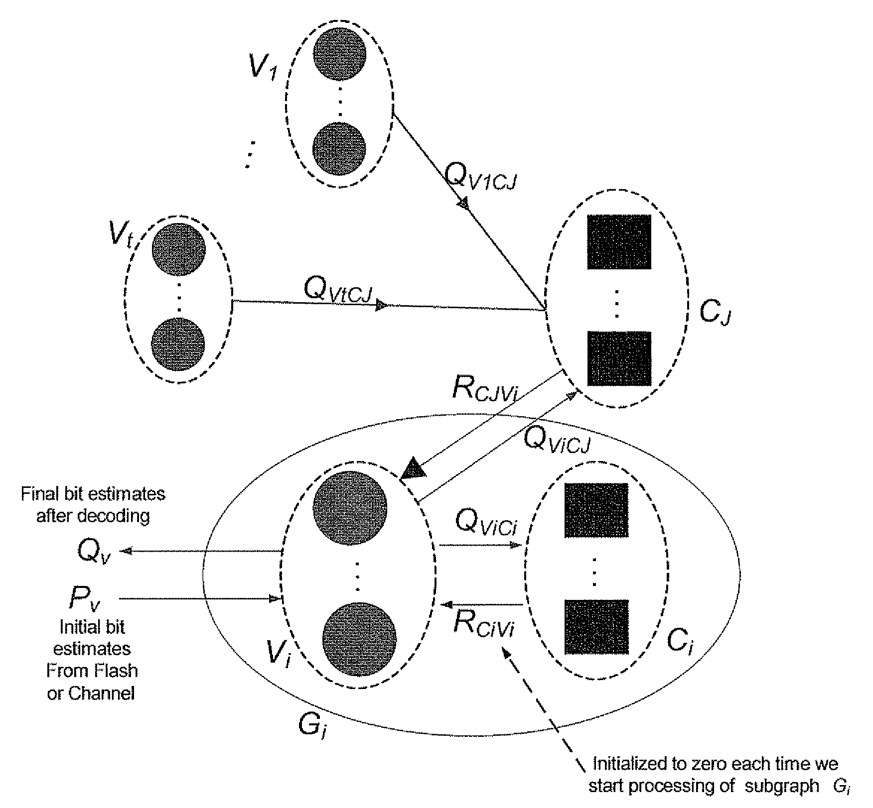
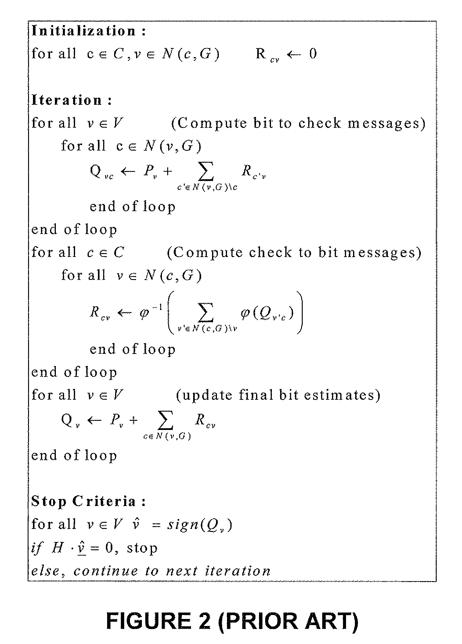
[0091]In conventional decoders for LDPC codes, the memory required by the decoder is proportional to the code length N (equal to the number of variable nodes in the code's underlying graph |V|) and to the number of edges in the code's underlying graph |E|. In efficient implementations (e.g. based on serially scheduled decoders), the required memory can be as small as (|V|+|E|)*bpm bits, where |V| is the number of bit estimations, |E| is the number of edge messages and bpm is the number of bits per message stored in the memory of the decoder (note that we assume here that the same number of bits is required for storing bit estimation and edge message, for the sake of simplicity, though this is not necessarily the case). The decoder presented herein uses much ...


PUM


Abstract

To decode, in a plurality of iterations, a representation, imported from a channel, of a codeword that encodes K information bits as N>K codeword bits, estimates of the codeword bits are updated by exchanging messages between N bit nodes and N−K check nodes of a graph. If the decoding has failed to converge according to a predetermined failure criterion and if the codeword bit estimates satisfy a criterion symptomatic of the graph including a trapping set, at least a portion of the messages are reset before continuing the iterations. Alternatively, if the decoding fails to converge according to a predetermined failure criterion, at least a portion of the messages that are sent from the bit nodes are truncated before continuing the iterations.

Description

FIELD AND BACKGROUND OF THE INVENTION[0001]Disclosed herein is a method and associated devices, for Low-Density Parity Check (LDPC) decoding, that overcomes non-convergence due to trapping sets.[0002]Error Correction Codes (ECCs) are commonly used in communication systems and in storage systems. Various physical phenomena occurring both in communication channels and in storage devices result in noise effects that corrupt the communicated or stored information. Error correction coding schemes can be used for protecting the communicated or stored information against the resulting errors. This is done by encoding the information before transmission through the communication channel or storage in the memory device. The encoding process transforms the information bits sequence into a codeword by adding redundancy to the information. This redundancy can then be used in order to recover the information from the possibly corrupted codeword through a decoding process.[0003]In both communicat...

Claims


Application Information

Patent Timeline
IPC IPC(8): H03M13/00G06F12/02G06F12/00
CPCH03M13/1111H03M13/3738H03M13/2951H03M13/1131
Inventor SHARON, ERANALROD, IDANLITSYN, SIMON
Owner RAMOT AT TEL AVIV UNIV LTD
Learn More