
Driving support device, driving support method and driving support program

Inactive Publication Date: 2009-12-24
AISIN AW CO LTD
View PDF4 Cites 11 Cited by
  • Summary
  • Abstract
  • Description
  • Claims
  • Application Information

AI Technical Summary

Benefits of technology

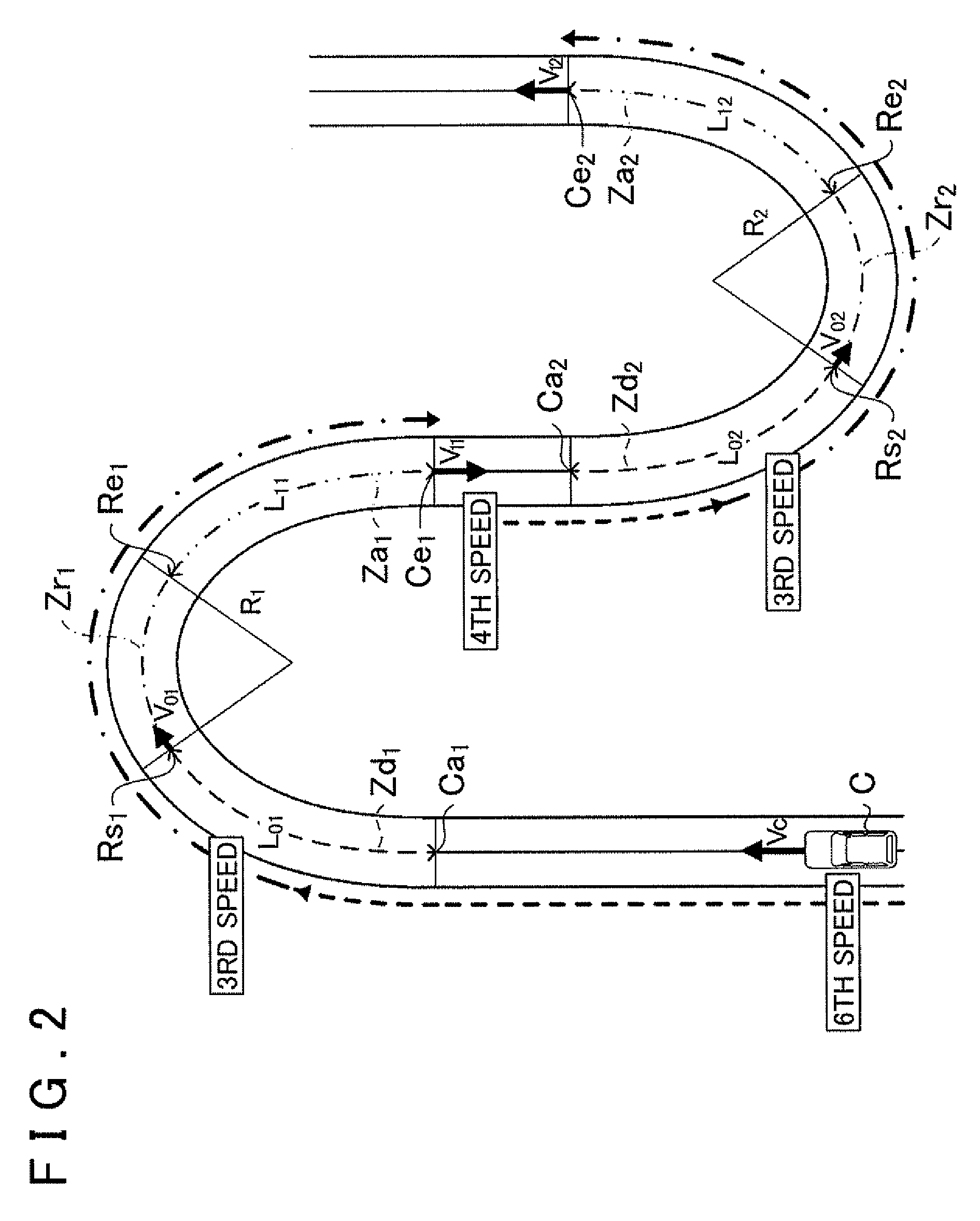
[0008]In order to achieve the above object, the present invention acquires a first acceleration gear ratio for accelerating a host vehicle in a first acceleration zone, and acquires a second acceleration gear ratio for accelerating the host vehicle in a second acceleration zone. By executing a control that sets the gear ratio of the host vehicle to the first acceleration gear ratio in a first deceleration zone, the gear ratio of the host vehicle becomes the first acceleration gear ratio before the host vehicle enters the first zone. Therefore, the host vehicle can travel the first zone in the first acceleration gear ratio, and also continue running in the first acceleration gear ratio even after traveling the first zone. However, when the host vehicle must decelerate with respect to the second zone while running in the first acceleration gear ratio, a control is executed that sets the gear ratio of the host vehicle to the second acceleration gear ratio.
[0012]The acceleration gear ratio obtaining unit is not limited provided that the first and second acceleration gear ratios can be acquired for accelerating the host vehicle after traveling the first and second zones, respectively. The first and second acceleration gear ratios are not limited provided that they are gear ratios capable of smoothly accelerating the host vehicle after respective travel through the first and second zones. Accordingly, the first and second acceleration gear ratios should be gear ratios capable of acceleration and continuing travel without generating sudden changes in speed or acceleration and without inducing unstable behavior in the host vehicle.
[0013]For example, various other configurations may be used in which the acceleration gear ratio is acquired based on an amount of acceleration for accelerating the host vehicle from the target vehicle speed for traveling each section to the recommended vehicle speed after traveling each section, provided that, for the respective first and second zones, a gear ratio is acquired that enables acceleration from the target vehicle speed to the recommended vehicle speed, and a gear ratio is also acquired that enables travel at a recommended vehicle speed faster than the target vehicle speed when the rotational speed of a drive source is equal to a specific value. In other words, by setting the gear ratio of the host vehicle to the first and second acceleration gear ratios before completing travel through the first and second zones, respectively, acceleration should be possible without changing the gear ratio at the acceleration phase after traveling the first and second zones. Thus, the host vehicle can be smoothly accelerated after traveling the first and second zones.
[0019]In other words, a point at which the control for changing to the second acceleration gear ratio is specified based on a predetermined deceleration, aid newly defining the point at the end point of the first acceleration zone shortens the length of the first acceleration zone compared to before the correction was performed. In addition, the speed assumed at the end point of the first zone newly set in the case of accelerating the host vehicle at the first required acceleration is multiplied by a predetermined coefficient to re-calculate the required acceleration for reaching the first recommended vehicle speed at the post-correction end point of the first acceleration zone, which is set as the first required acceleration. Consequently, the impression received by the driver during travel with consecutive acceleration and deceleration can be fine-tuned. In particular, when the coefficient is less than 1, more gradual acceleration and deceleration can be achieved compared to the case of no correction, which can create the impression of smooth travel. Obviously, even if the coefficient is greater than 1, adjustment of the value makes it possible to vary the impression of the driver, in terms of emphasizing safe, smooth, or sporty driving.

Problems solved by technology

On a road with consecutive specific zones where travel at a specific target vehicle speed is desired, the related art was unable to support smooth acceleration and deceleration between the specific zones.
In the case of acceleration after decelerating to the target vehicle speed before the specific zone and then traveling through the specific zone, switching the gear speed in accordance with a target deceleration may result in a gear speed unsuitable for increasing speed at the acceleration phase.
As a consequence, smooth acceleration cannot be achieved.

Method used


Image

  • Driving support device, driving support method and driving support program
  • Driving support device, driving support method and driving support program
  • Driving support device, driving support method and driving support program

Examples


Embodiment Construction

[0037]Embodiments of the present invention will be explained in the order shown below.

(1) Configuration of Navigation Device

(2) Driving Support Processing

[0038](2-1) Parameter Calculation Processing

[0039](2-2) Vehicle Deceleration Processing

[0040](2-3) Deceleration Start Determination Processing

[0041](2-4) Deceleration Control Processing

[0042](2-5) Vehicle Speed Restriction Processing

[0043](2-6) Gear Ratio Selection Processing

[0044](2-7) Gear Ratio Acquisition Processing

(3) Operation Example

(4) Other Embodiments

[0045](1) Configuration of Navigation Device

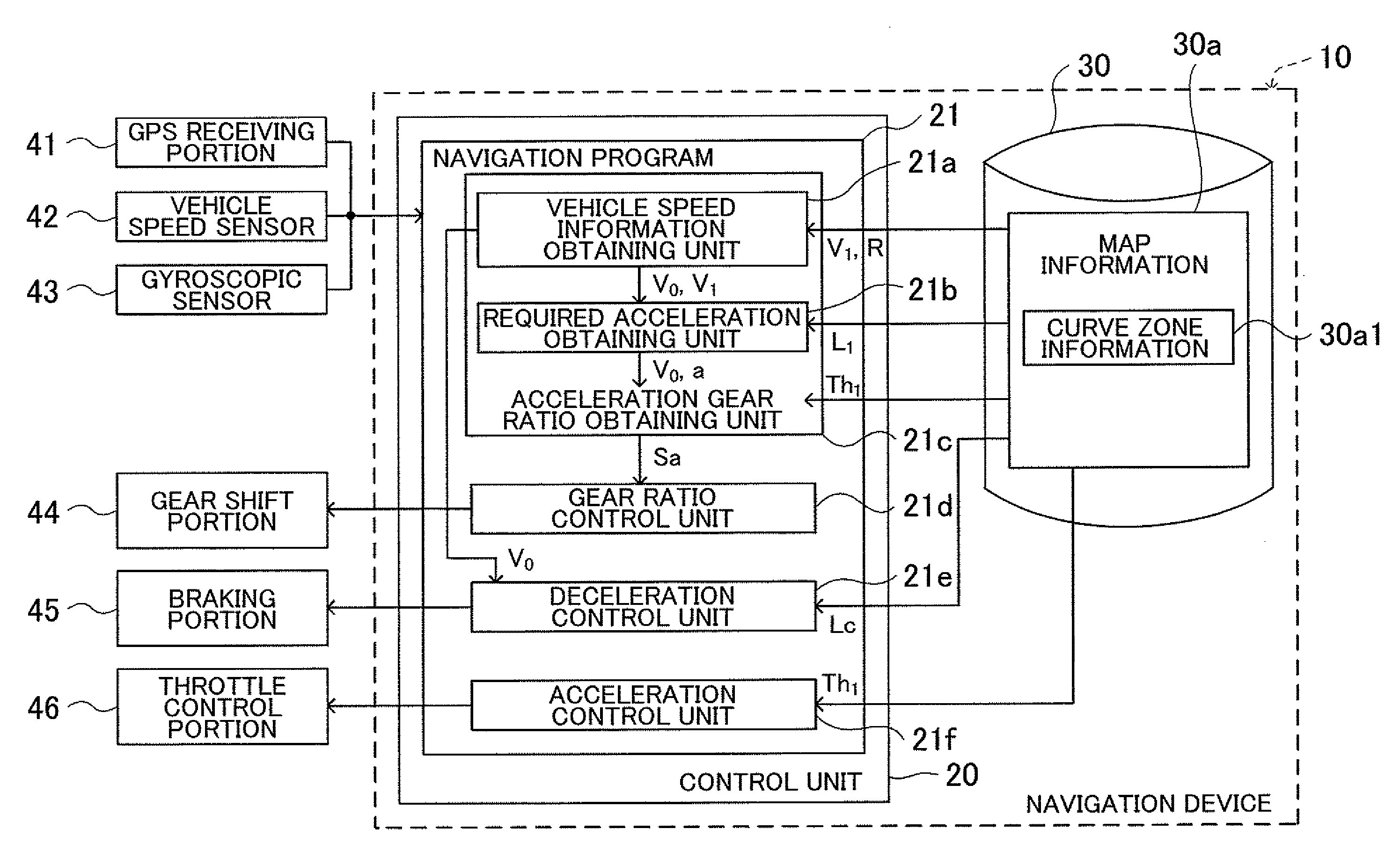
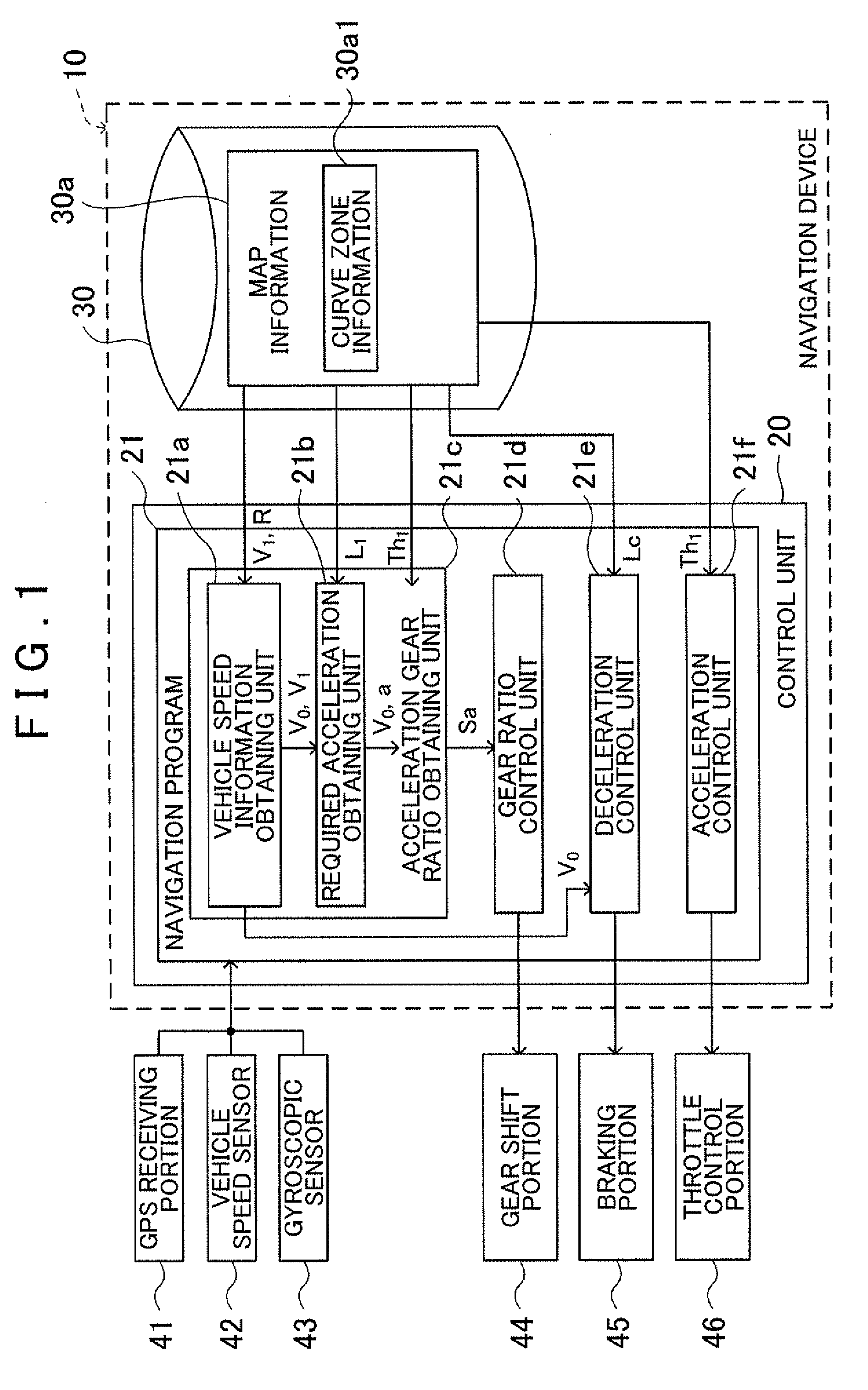
[0046]FIG. 1 is a block diagram that shows the configuration of a navigation device 10 that incorporates a driving support device according to the present invention. The navigation device 10 includes a storage medium 30 and a control unit 20 that includes a CPU, a RAM, a ROM, and the like. The control unit 20 executes programs that are stored in the storage medium 30 and the ROM. In the present embodiment, one such executable progra...


PUM


Abstract

A first acceleration gear ratio is acquired for accelerating a host vehicle in a first acceleration zone following a first zone ahead of the host vehicle, and a second acceleration gear ratio is acquired for accelerating the host vehicle in a second acceleration zone following a second zone ahead of the first zone. A control is executed to set the gear ratio of the host vehicle to the first acceleration gear ratio in a first deceleration zone in order to decelerate the host vehicle before entering the first zone. A control is executed to set the gear ratio of the host vehicle to the second acceleration gear ratio when the host vehicle must decelerate with respect to the second zone while traveling in the first acceleration gear ratio.

Description

INCORPORATION BY REFERENCE[0001]The disclosure of Japanese Patent Application No. 2008-161615 filed on Jun. 20, 2008 including the specification, drawings and abstract is incorporated herein by reference in its entirety.BACKGROUND OF THE INVENTION[0002]The present invention relates to a driving support device, a driving support method, and a driving support program that support driving of a vehicle.DESCRIPTION OF THE RELATED ART[0003]In a conventional device for controlling the braking force of a vehicle, a vehicle is decelerated by switching to a gear speed whereby a deceleration closest to a target deceleration, without exceeding the target deceleration, may be obtained, and using an engine brake at the gear speed; insufficient deceleration by the engine brake is compensated by a brake (see Japanese Patent No. 3858952).SUMMARY OF THE INVENTION[0004]On a road with consecutive specific zones where travel at a specific target vehicle speed is desired, the related art was unable to su...

Claims


Application Information

Patent Timeline
IPC IPC(8): F16H61/02B60T8/32F16H59/44F16H59/48F16H59/66F16H63/50G08G1/16
CPCB60W2720/106F16H2059/186F16H2059/666B60W10/06B60W2550/402B60W10/184B60W2550/143B60W30/18072B60W10/115F16H61/0213Y10T477/692B60W2550/146F16H2061/0216F16H59/66B60W2552/30B60W2552/20B60W2556/50B60W30/18145
Inventor KONDOU, YOSHITOMIYAJIMA, TAKAYUKITAKEUCHI, ATSUSHI
Owner AISIN AW CO LTD
Learn More