Method and apparatus for high mass concentration NANO particle generation

a nano-particle, high-mass concentration technology, applied in the direction of applications, biocide, aerosol delivery, etc., can solve the problems of inability to determine the specific toxicity of many of these materials when compared to other materials, and the approach is generally undesirable for generating aerosols for inhalation studies

Active Publication Date: 2009-12-24
BATTELLE MEMORIAL INST
View PDF2 Cites 3 Cited by
  • Summary
  • Abstract
  • Description
  • Claims
  • Application Information

AI Technical Summary

Benefits of technology

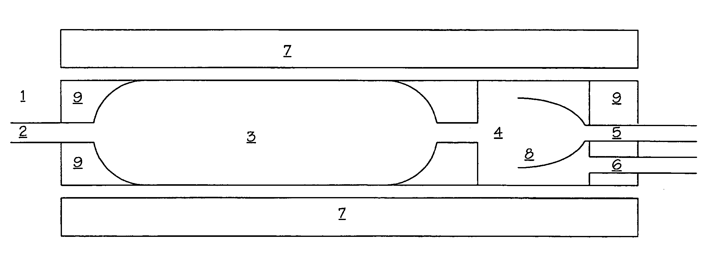
[0011]Vaporized materials leaving the vaporization chamber enter the input end of a dilution chamber of the furnace tube. The dilution chamber is designed such that the bulk materials are rapidly condensed as they exit the furnace tube in a manner that prevents them from agglomerating with one and another. In this manner, the present invention successfully forms nano sized particles at high concentrations and at high levels of purity.
[0013]In a preferred embodiment of the present invention, the rapid transport of the vaporized materials through the dilution port is assisted by providing a cup receiver having an input end within the dilution chamber and an output end used as the output end of the dilution chamber. Generally, a “cup receiver” is any tube having a relatively large entrance at one end, and a relatively smaller exit at the opposite end.
[0014]The cup receiver is positioned within the dilution chamber such that vaporized materials entering the dilution chamber traverse a short distance of open space, and then enter the relatively large opening of the cup receiver. The additional gas flow introduced through the gas port also enters the cup receiver at the relatively large end. In this manner, the gas flow and the vaporized materials are combined within the cup receiver in a manner that minimizes the dilution of the vaporized materials. The dilution materials are thus moved through the cup receiver as quickly as possible, exiting at the output end, thus maximizing the temperature drop and cooling the vaporized materials as quickly as possible.
[0015]Modeling of the gas flow in the preferred embodiment has shown that the dilution materials are moved through the cup receiver essentially along a linear pathway, thus maximizing the temperature drop thereby cooling the vaporized materials as quickly as possible.
[0017]The present invention also contemplates the use of an extraction port positioned between the solid aerosol disperser and the vaporization chamber. The extraction port is used to extract a portion of the gas flow prior to introduction into the vaporization chamber. The extraction port includes a separator, where a portion of the bulk material having relatively larger particle sizes is separated and extracted prior to introduction into the vaporization chamber. This assists in reducing the particle size further prior to introducing the particles to the inlet of the furnace tube. The separator may be a cyclone, an impact device, or combinations thereof.
[0022]As described above, when the second gas is introduced into the dilution chamber, the flow of the second gas is sufficient to eject the bulk material from the exit, thereby condensing the bulk material into nano sized particles. The nano sized particles are then cooled to a temperature sufficient to prevent oxidation, whereupon a flow of oxygen may be introduced without oxidizing the nano sized particles. By selecting the inert gases as N2, and adding an amount of oxygen sufficient such that the total amount of oxygen in the resulting gas flow greater than about 19.5%, the present invention allows the creation of an aerosol of nano particles of C60 in a gas flow essentially identical to air. Of course, other trace gases also found in air may also be included in the oxygen flow, thereby making the resultant gas a perfect match with air, but such is generally not required for effective toxicology studies. Exposing living organisms to this aerosol thereby enables inhalation toxicology testing of Buckminster fullerenes.

Problems solved by technology

Despite the fact that many different nano scale materials are already in use in consumer products, the ability to determine the specific toxicity of many of these materials is still limited when compared to other materials.
Such approaches are generally undesirable for generating aerosols for inhalation studies, as the toluene contained within the aerosolized materials is incompatible with inhalation studies.

Method used


Image

  • Method and apparatus for high mass concentration NANO particle generation
  • Method and apparatus for high mass concentration NANO particle generation
  • Method and apparatus for high mass concentration NANO particle generation

Examples


Embodiment Construction

[0050]The final schematic of the system used to generate the aerosols of C60 nano particles is depicted in FIG. 12.

[0051]To demonstrate one embodiment of the present invention, a series of experiments were conducted using C60 particles supplied by SES Research, Houston, Tex. The bulk material consisted of dark colored, fine particles and had been stored at room temperature. The bulk material was milled in a Wig-L-Bug (Crystal Laboratories, Garfield, N.J.) for about 2 minutes before feeding to the generator.

[0052]The solid air disperser used to initially generate C60 aerosols for these studies is available from the assignee herein, Battelle Memorial Institute, Columbus Ohio. Briefly, as shown in FIGS. 2, 3a and 3b, it consisted of a rotary dust feed device 10 coupled to a single jet Particle Attrition Chamber (PAC) 14.

[0053]As shown in FIG. 2, the rotary dust feed device 10 consists of a drum (not visible), a body 11, a cap 12 and a drum rotation driver 13. The drum, which rotated du...


PUM

PropertyMeasurementUnit
Temperatureaaaaaaaaaa
Fractionaaaaaaaaaa

Abstract

A method and apparatus for generating nano particles, including but not limited to nano particles of Ceo, at high concentration. The invention uses a solid aerosol disperser in communication with a furnace tube having a vaporization chamber and a dilution chamber. A heating element surrounds the furnace tube. Heat from the heating element heats bulk materials contained within a gas flow in the vaporization chamber to a temperature sufficient to convert the bulk materials to a vapor phase. Vaporized bulk materials are then moved to a dilution chamber, where an inert gas is introduced through a dilution gas port. The flow of the inert gas into the dilution chamber through the dilution gas port is sufficient to eject the bulk material from the exit of the dilution chamber, thereby condensing the bulk material into nano sized particles in a gas flow of sufficient volume to prevent agglomeration of the nano sized particles.

Description

RELATED APPLICATIONS[0001]This invention claims priority to, and incorporates by reference, the entire contents of U.S. Provisional Application No. 60 / 779,119, filed Mar. 3, 2006, and U.S. Provisional Application No. 60 / 837,057, filed Aug. 10, 2006.TECHNICAL FIELD[0002]This invention relates to methods and apparatus for generating nano-sized particles. In this form, these materials are suitable for use in applications requiring high concentration and high purity, including, but not limited to, inhalation toxicology studies, manufacturing applications, occupational safety and health studies, and as drug delivery systems. The invention is particularly well suited and enables the generation of high concentrations of nano-sized particles of C60 aerosols.BACKGROUND OF THE INVENTION[0003]Despite the fact that many different nano scale materials are already in use in consumer products, the ability to determine the specific toxicity of many of these materials is still limited when compared ...

Claims


Application Information

Patent Timeline
IPC IPC(8): A61K9/12C01F17/00C01B31/02C01G23/047B01J8/00
CPCB82Y30/00B82Y40/00C01B31/0206C01G23/047C01P2004/64C01P2002/82C01P2002/85C01P2004/04C01P2004/52C01P2002/72C01B32/15B82B3/00C01B32/05
Inventor GUPTA, AMITFORSYTHE, WILLIAM C.CLARK, MARK L.
Owner BATTELLE MEMORIAL INST
Why Eureka
Try Eureka