
Method for producing structures of complex shapes of composite materials

a composite material and complex shape technology, applied in the direction of valve details, slide valves, lamination, etc., can solve the problems of complex shape parts, inability to produce cores made of several components in practice, and inability to meet the requirements of use, so as to achieve good material soundness and better control of dimensions

Inactive Publication Date: 2009-12-17
EADS FRANCE
View PDF15 Cites 39 Cited by
  • Summary
  • Abstract
  • Description
  • Claims
  • Application Information

AI Technical Summary

Benefits of technology

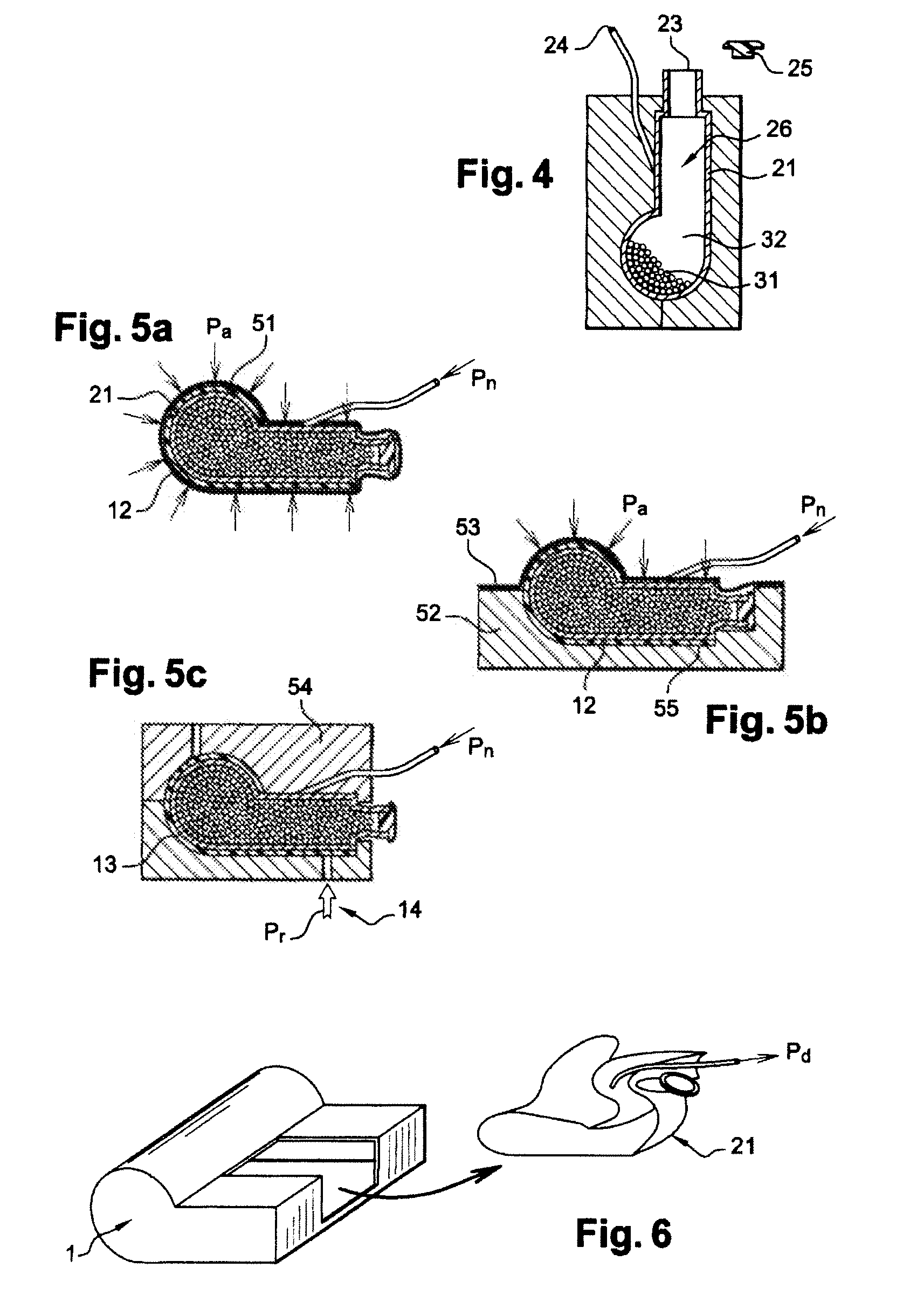
[0014]The process for producing a part made from a composite comprising fibers with a resin that changes from a pasty or liquid state to a solid state in the course of a curing phase and comprising a partially sealed zone, in a volume corresponding completely or partly to the partially sealed zone is occupied by a core, said core comprising a bladder made of a flexible material that has an outer surface that delimits a volume of the core, the shapes and the dimensions of which are in keeping with the volume of the partially sealed zone and having an inner surface that determines a volume of the bladder, which volume of the bladder is filled with a granular solid material and an intergranular fluid, is in which a pressure is exerted on the inner surface of the bladder by the granular solid material and / or the fluid so that the volume of the core is modified in a controlled manner before the composite is completely cured. This modification of the volume of the core before the resin is cured has the effect of balancing and homogenizing the pressures over the various parts used that makes it possible to obtain a shape of the part within the desired tolerances and therefore to prevent local deformations of the part, and also a good material soundness.
[0016]To avoid deformations of the part during its production despite the increase in the temperature in the course of the curing phase of the resin, the volume of the core is modified in a controlled manner by choosing the granular solid material from materials that have a thermal expansion coefficient close to the thermal expansion of the composite of the part.
[0022]In particular, the pressure Pn is increased to a value substantially equal to a pressure Pa used to keep the fibers in the core during the curing phase of the resin, having the effect of balancing the pressure exerted on the part by a pressurized bladder.
[0023]In particular, the pressure Pn is increased to a value at least equal to a pressure Pr for injecting the resin, for example when the process uses a transfer of resin to dry fibers, in order to control the pressure of the resin Pr, to make it homogeneous, to allow better control of the dimensions, to obtain a good material soundness, and to prevent the surface of the core and therefore the wall of the part from being deformed by the pressure of the resin.

Problems solved by technology

Parts having complex shapes sometimes make it necessary to use molds, certain components of which may be stuck in the part at the time it is demolded.
Thus, it is frequently hollow or enveloping shapes that make it necessary for the mold to comprise particular components or cores which fill the hollow shapes of the part while it is being produced.
However, such cores made of several components fitted together cannot always be produced in practice and are always more expensive than molds made from a single component and may prove very complex both at the design level and at the implementation level.
In this case, the difficulty is in finding a material to produce the core which is economically acceptable, is capable of withstanding the sometimes extreme conditions encountered during the process for producing the part made from a composite, is sufficiently solid to withstand the handling and mechanical stresses during the preparation of the part while satisfying the strict shape tolerances and can be removed mechanically or by melting without risk of damaging the part or be dissolved by water or by another solvent compatible with the material of the part.
These combinations of conditions are not always possible and in any case it is necessary to manufacture as many cores or sets of cores as parts to be produced which is, along with the phase of removing the core and of meeting current hygiene and safety conditions, expensive from an industrial point of view.
The failing of cores that use a deformable material is their dimensional instability due to their low rigidity which does not make it possible to obtain reproduction, within the tolerances required by certain applications, of the results during the manufacture of the parts.
Furthermore, the low necking coefficient does not make it possible to solve situations with significant variations in the cross section of the core, in particular when the core must be removed through an opening of reduced cross section.
One problem that is faced with this type of production is the dimensional quality of the part produced which may be insufficient.
Although these variations in dimensions are not troublesome for widely available composite parts such as, for example, air conditioning piping, they are generally unacceptable for producing high-performance composite parts, such as, for example, structural parts with tight geometrical tolerances intended for a precise assembling and of which the dimensional characteristics are often critical as is the structural soundness of the material of the finished part which must not contain gas bubbles or porosities, nor pockets of resin, nor “dry” fibers, phenomena that lead to high levels of scrap during manufacture and are equally sources of delamination when the part is subjected to operating stresses which leads to oversizing the parts, the structural strength of which must be / is essential.

Method used


Image

  • Method for producing structures of complex shapes of composite materials
  • Method for producing structures of complex shapes of composite materials
  • Method for producing structures of complex shapes of composite materials

Examples


first embodiment

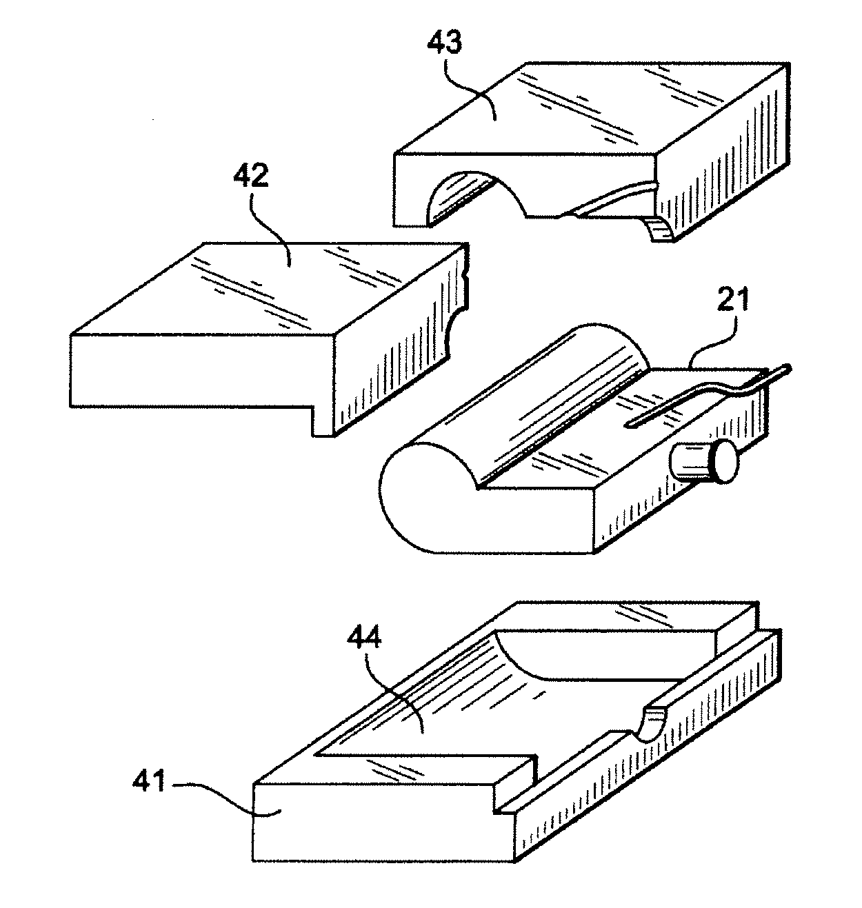
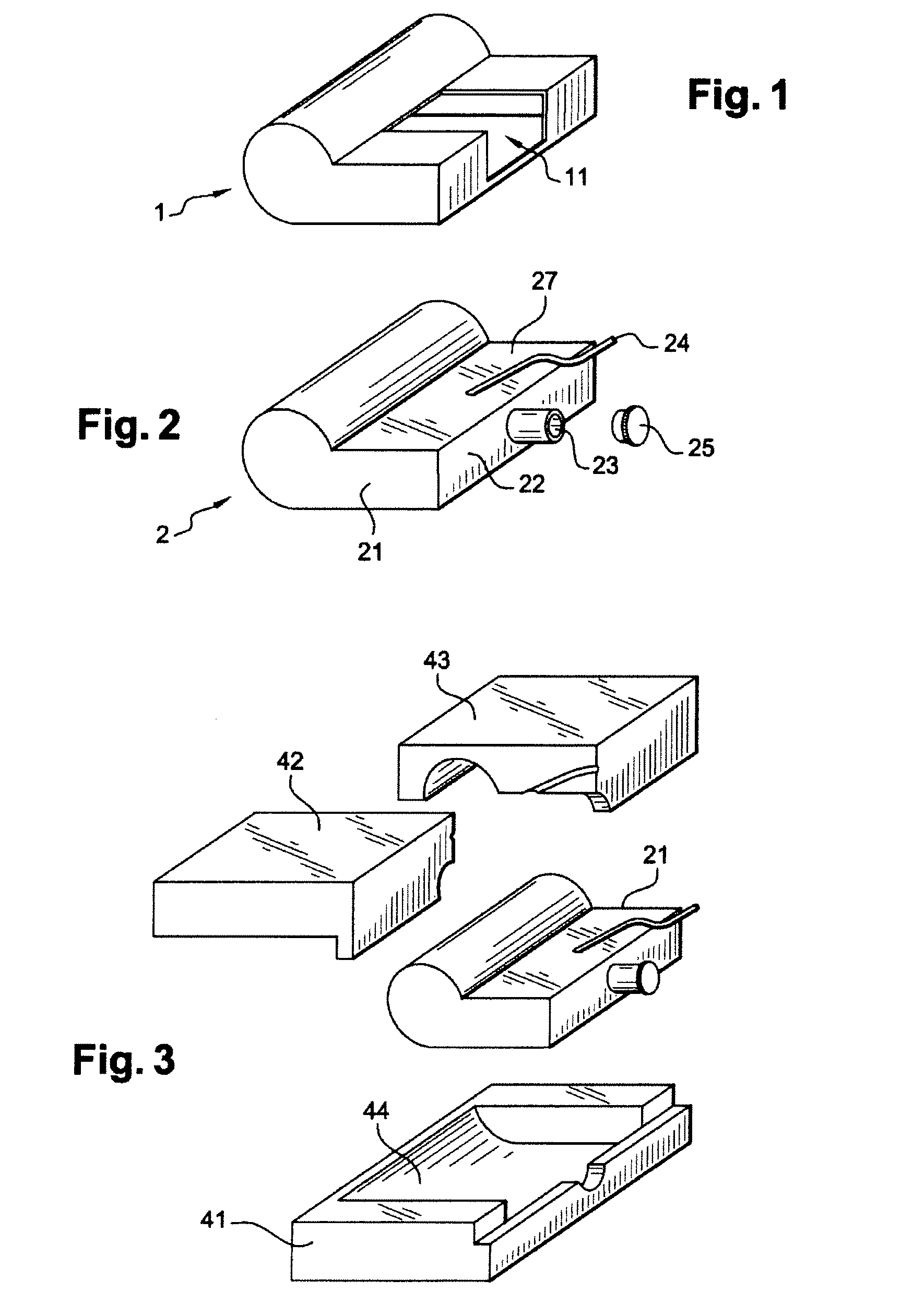
[0050]In the process according to the aspects of the disclosed embodiments, when the various parts of the mold and the fibers 12, 13 have been positioned and where appropriate the resin 14 injected, the pressure Pn in the core 2 is increased so that the pressure Pa exerted by the other means of the mold when these means are means that have a certain flexibility, for example a bladder 51, 53 as illustrated in FIGS. 5a and 5b or an elastomeric counterform (not shown), in particular those located on the face of the part opposite the face in contact with the core, or balanced.

second embodiment

[0051]In the process according to the aspects of the disclosed embodiments, when the various parts of the mold 52, 54 and the fibers 12, 13 have been positioned and where appropriate the resin 14 injected, the pressure Pn in the core 2 is increased so that the core compresses the composite 12, 13 against the walls of the mold 52, 54 when this is a mold having rigid walls. In particular, when the part is produced according to a resin transfer process as illustrated in FIG. 5c, after injecting the resin 14 until the fibers 13 are completely impregnated and feeding at a vacuum level Pr, the openings for injecting the resin 14 are closed and the pressure Pn is increased in the bladder of the core to a value greater than or equal to the pressure value Pr in order to compact the composite and homogenize the pressure.

[0052]By this process, on the one hand a better pressurization of the fiber 12, 13 comprising the resin is ensured which has the effect of greatly reducing the risk of the pre...


PUM

PropertyMeasurementUnit
Thermal expansion coefficientaaaaaaaaaa
Temperatureaaaaaaaaaa
Pressureaaaaaaaaaa

Abstract

A method for producing a composite material part having a so-called non-strippable shape includes producing mold components, or cores, which are to be extracted from the part after the composite material has been cured. In a first step a core is produced from an elastomeric bladder the granular solid material and the bladder is depressurized. In a second step, after setting the core and the composite material the volume of the core is modified in a controlled manner for example by selecting the solid granular material based on its thermal expansion properties or by acting on the pressure in the bladder.

Description

CROSS-REFERENCE TO RELATED APPLICATIONS[0001]This application is the National Stage of International Application No. PCT / EP2007 / 052621, International Filing Date 20 Mar. 2007, which designated the United States of America and which International Application was published under PCT Article 21 (2) as WO Publication No. WO2007 / 107552 A1 and which claims priority to French Application No. 06 / 50956, filed 20 Mar. 2006, the disclosures of which are incorporated herein by reference in their entireties.BACKGROUND[0002]1. Field[0003]The disclosed embodiments relate to the field of producing parts of complex shapes made of composites that require molds during the manufacturing operations. More particularly, the process according to the aspects of the disclosed embodiments uses mold components that are trapped inside the part at the time it is produced and that are then extracted therefrom in order to make it possible to produce parts that are said to be non-demoldable.[0004]2. Brief Descripti...

Claims


Application Information

Patent Timeline
IPC IPC(8): B29C70/44
CPCB29C33/3821B29C33/505B29C70/44F16K43/00F16K3/04F16K13/00F16K27/04B29C70/446
Inventor CAVALIERE, FREDERICKGUITTON, MAURICEGUITTON, SEVERINE
Owner EADS FRANCE
Learn More