
Method of Breaking Off Casting

a technology of breaking and casting, applied in the direction of grain treatment, etc., can solve the problems of increasing the cost due to extra materials, unexpected load applied to the mobile cutter device, etc., and achieve the effect of reducing the size and weight, ensuring the durability of the damper, and lessening the load application to the damper

Inactive Publication Date: 2009-12-17
OKUYA YASUAKI
View PDF2 Cites 0 Cited by
  • Summary
  • Abstract
  • Description
  • Claims
  • Application Information

AI Technical Summary

Benefits of technology

[0007]An invention set forth in claim 1 is configured in such a manner that a discharge port formed below second and first cutter devices is closed or opened via an automatically adjustable damper. Because the discharge port can be opened and closed arbitrarily using an additional element, such as a load, it is possible to lessen a load application to the damper. Accordingly, it becomes possible to ensure the durability of the damper and reduce both the size and the weight. Also, by adopting the configuration to satisfy the requirements to the damper, claim 1 achieves actual advantages that it can contribute to the management strategy of facilities by improving the economical efficiency and providing the most reasonable price and functionalities as an industrial machine.
[0008]In addition, the invention set forth in claim 1 is capable of allowing the crushed and broken recycled cast products to accumulate and / or preventing the accumulation via the damper that automatically opens and closes. Hence, it has actual advantages that a fuel needed for the melting is saved and / or the environment can be protected while making the processing of the useless cast raw materials easier and faster and ensuring the melting conditions and the economic efficiency, a stock of the useless cast raw materials can be lessened, and the spaces within the facilities can be utilized more efficiently, and the like.

Problems solved by technology

Accordingly, there is a possibility that an unexpected load (burden) is applied to the mobile cutter device.
This possibility poses a problem in durability, which raises a need to make the device robust enough to withstand such an expected load, or increases the cost due to extra materials required in order to ensure the durability and the robustness of the device.
Accordingly, the summary (2) has a problem in the point of discharging the recycled cast freely and arbitrarily from the discharge port.

Method used


Image

  • Method of Breaking Off Casting
  • Method of Breaking Off Casting
  • Method of Breaking Off Casting

Examples


Embodiment Construction

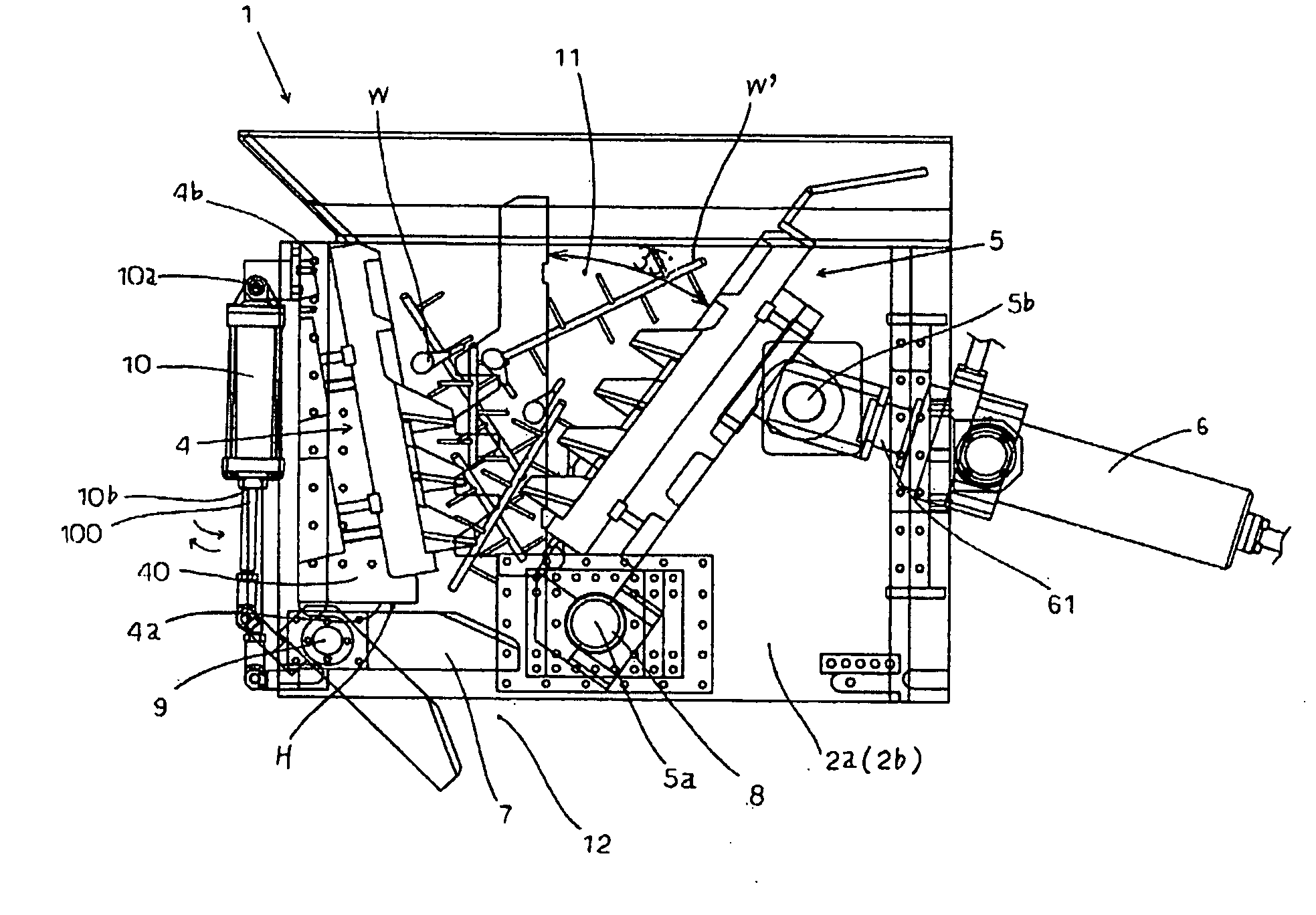
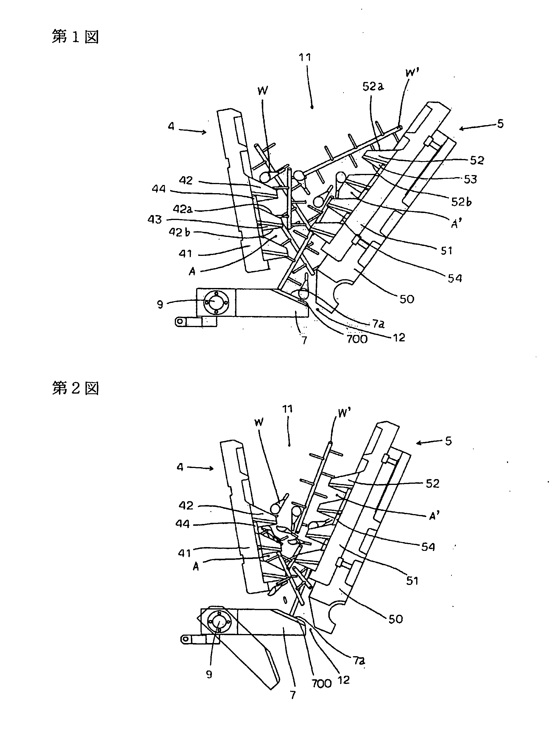
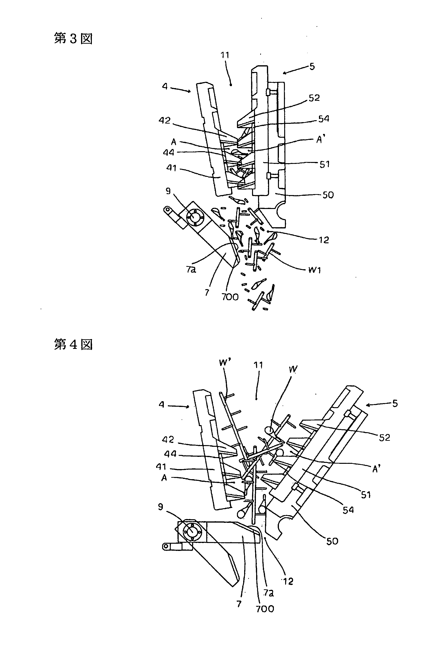
[0037]Hereinafter, an example of crushing and / or breaking apparatus used in a method of the invention will be described on the basis of the drawings. A crushing and / or breaking device 1 is chiefly composed of a frame 3 formed of side plates 2a and 2b and a bridging plate 2c and configured to open at the top and the bottom, a first cutter deice 4 (fixed cutter device) and a second cutter device 5 (mobile cutter device) provided to the frame 3, a cylinder 6 that allows the second cutter device 5 to move forward and retract, and a damper 7.

[0038]Initially, raw materials W are placed inside from a placement opening 11 formed above by the first cutter device 4 and the second cutter device 5 opposing the first cutter device 4. Then, the second cutter device 5 moves along a circular trajectory via mobile means having a fulcrum 5b on the upper side of the second cutter device 5 and presses the placed raw materials W. Meanwhile, the raw materials W are crushed and broken as they are broken b...


PUM


Abstract

A breaking method in the related art includes first and second cutter devices each opening in the top and bottom faces, a number of projection-shaped first cutters provided to the first cutter device so as to protrude in a staggered fashion, the second cutter device and a number of projection-shaped second cutters provided to the second cutter device so as to protrude in a staggered fashion having a fact-to-face relation with the first cutter device and the first cutters, respectively, and mobile means that allows the second cutter device to move. Weirs and runners that are now useless and useless cast raw materials (referred to as useless cast raw materials), etc. are placed inside from a placement opening defined between the first cutter device and the second cutter device when the second cutter device is retracted. The useless cast raw materials are then crushed and broken using a fitting relation between the second cutters of the second cutter device that is moved forward by the cylinder and the first cutters of the first cutter device. In a case where an abnormal load is applied to the second cutters (second cutter device) in motion, the second cutters are retracted or stopped by the action of the safety mechanism. Broken recycled cast products (recycled cast) are discharged by natural fall from a discharge port (outlet) defined between the first cutter device and the second cutter device when the second cutter device is retracted.The invention is a cast breaking method for crushing and breaking a useless cast raw material by placing the useless cast raw material inside from a placement opening formed above by a first cutter device provided with a first cutter that converges toward a tip end and a second cutter device facing the first cutter device and provided with a second cutter that faces the first cutter and converges toward a tip end as well as having a fulcrum shaft on a lower side by means of a pressing action to press the placed useless cast raw material through a movement of the second cutter device along a circular trajectory using mobile means having a fulcrum shaft on an upper side of the second cutter device and a breaking action between the first and second cutters, characterized in that:a part of the useless cast raw material placed inside from the placement opening is held via a damper that is openable and closable and positioned at a discharge port below the first and second cutter devices so as to avoid falling of the useless cast raw material from the discharge port below and to avoid accumulation of a crushed and broken recycled cast product by opening the damper using mobile means.

Description

TECHNICAL FIELD[0001]The present invention relates to a breaking method of cast, such as lengthy objects, and provides a fast cast breaking method that ensures optimal size, shape, and weight of recycled cast products (recycled cast raw materials) from useless cast raw materials (useless cast).BACKGROUND ART[0002]The cast breaking (crushing) method of the title and cutters most suitable to this method have been disclosed by the applicant of the present application in Japan, the United States, and Europe. Such disclosures include, for example, “hydraulic crushing and breaking apparatus of weirs, runners, and useless products for casting” in JP-A-6-106083,“cast breaking method and cutter structure” in JP-A-2002-224580, “crushing-breaking apparatus” in U.S. Pat. No. 5,791,573, and “an apparatus for crushing-breaking useless casting products using a fixed and a rocking cutter device and method for coating said cutting devices” in EP-A-0919283. The basic structures of these prior arts wi...

Claims


Application Information

Patent Timeline
Patent Type & Authority Applications(United States)
IPC IPC(8): B02C1/00
CPCB02C1/10B02C1/02
Inventor OKUYA, YASUAKI
Owner OKUYA YASUAKI
Learn More