
Ball grid array cleaning system

a cleaning system and integrated circuit technology, applied in the field of integrated circuit assembly techniques, can solve the problems of excessive solder, resin, or other debris, affecting the cleaning effect, and presenting an arduous task, so as to reduce repetitive motion injuries, reduce the height of materials, and improve the cleaning

Inactive Publication Date: 2009-12-10
RAYTHEON CO
View PDF25 Cites 2 Cited by
  • Summary
  • Abstract
  • Description
  • Claims
  • Application Information

AI Technical Summary

Benefits of technology

[0005]In accordance with the present invention, the disadvantages and problems associated with ball grid array cleaning systems have been substantially reduced or eliminated.
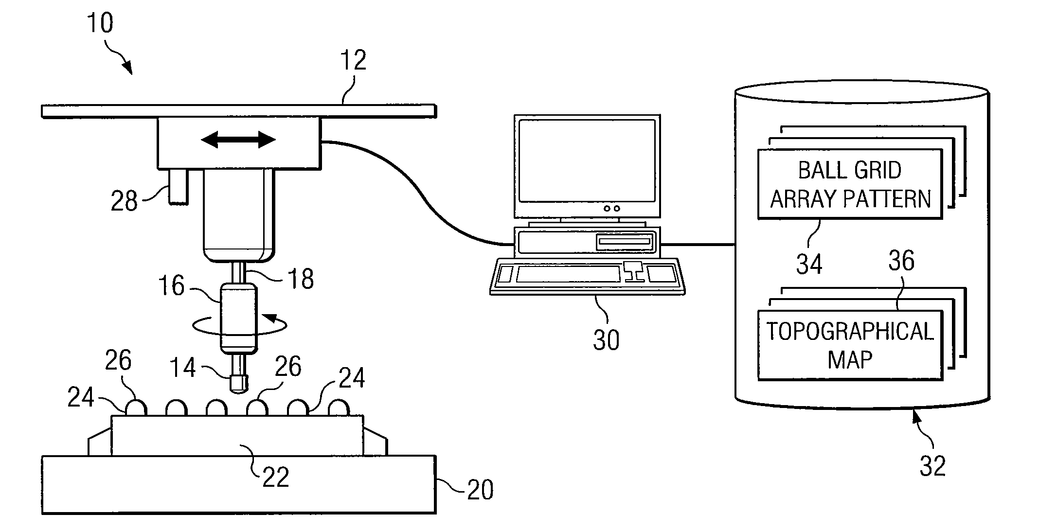
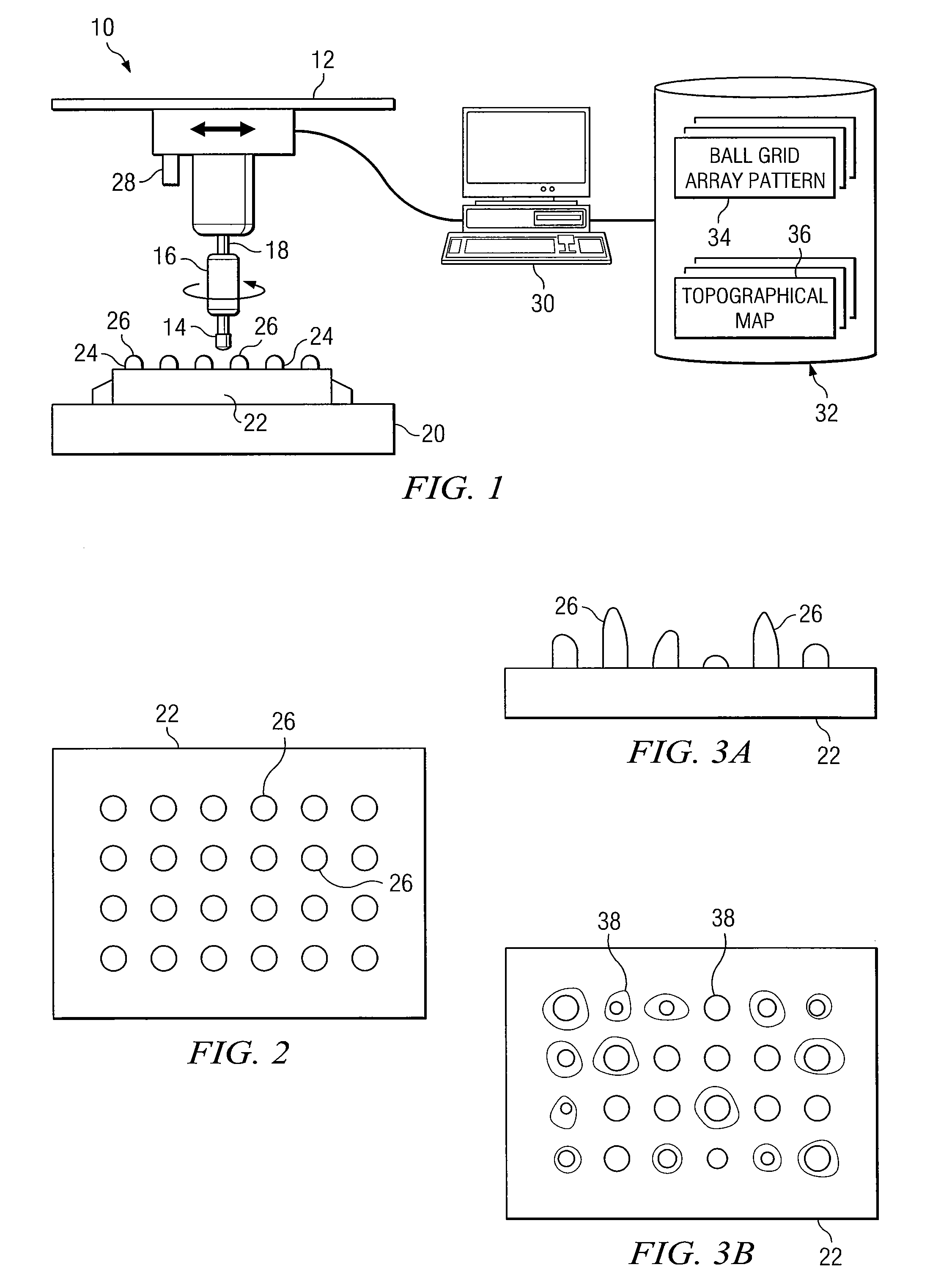
[0006]In certain embodiments, a system for cleaning ball grid arrays is provided. The system may include a platform upon which an integrated circuit is mounted. The integrated circuit may have a plurality of terminals arranged in a ball grid array pattern on a surface of the integrated circuit. The system also includes a machining bit and a computer system. The computer system may store the ball grid array pattern and a topographic map of the surface of the integrated circuit and control the machining bit such that the machining bit removes excess material from the plurality of terminals based at least in part upon the ball grid array pattern and the topographical map.
[0008]Technical advantages of certain embodiments of the present invention include reduction of repetitive motion injuries for workers removing excess material, the ability to achieve substantially uniform height of material on an integrated circuit to provide good electrical connections, and substantial savings in time and effort to reuse integrated circuits removed from a circuit board. Other technical advantages of the present invention will be readily apparent to one skilled in the art from the following figures, descriptions, and claims. Additionally, while specific advantages have been enumerated above, various embodiments may include all, some, or none of the enumerated advantages. The following technical advantages may be achieved by some or all of the embodiments of the present invention.

Problems solved by technology

Relatively complex integrated circuits (ICs) are often configured with numerous terminals.
Removal of an integrated circuit from a circuit board typically leaves excess solder, resin, or other debris that may hinder its assembly onto another circuit board.
Because ball grid arrays may have numerous terminals, this process may present an arduously long task.
Removal and cleaning the material from the terminals manually can lead to repetitive motion injuries for workers.
Manual removal of the excess material also leads to material that may not be uniform in height or topography.

Method used


Image

  • Ball grid array cleaning system
  • Ball grid array cleaning system
  • Ball grid array cleaning system

Examples


Embodiment Construction

[0017]Integrated circuits having terminals arranged in a ball grid array may provide several advantages. For example, these terminals may be relatively easier to assemble on substrates, such as circuit boards, than pin grid array (PGA) devices due to insertion problems associated with placement of numerous pins through a corresponding numerous quantity of holes. Integrated circuits incorporating a ball grid array suffer, however, in that the material on the terminals should be relatively co-planar with one another to form a good electrical connection to a printed circuit board or other components during manufacture.

[0018]FIG. 1 shows one embodiment of a ball grid array cleaning system 10 that may be used to clean material deposited on terminals arranged in a ball grid array. Ball grid array cleaning system 10 includes a computer-aided manufacturing tool 12 that is configured with a machining bit 14. Machining bit 14 may be coupled to computer-aided manufacturing tool 12 via collar 1...


PUM


Abstract

In certain embodiments, a system for cleaning ball grid arrays is provided. The system may include a platform upon which an integrated circuit is mounted. The integrated circuit may have a plurality of terminals arranged in a ball grid array pattern on a surface of the integrated circuit. The system also includes a machining bit and a computer system. The computer system may store the ball grid array pattern and a topographic map of the surface of the integrated circuit and control the machining bit such that the machining bit removes excess material from the plurality of terminals based at least in part upon the ball grid array pattern and the topographical map.

Description

CROSS-REFERENCE TO RELATED APPLICATION[0001]This application claims the benefit of priority under 35 U.S.C. §119(e) of U.S. Provisional Application 61 / 059,511 filed Jun. 6, 2008.TECHNICAL FIELD OF THE INVENTION[0002]This disclosure generally relates to integrated circuit assembly techniques, and more particularly, to a cleaning system for integrated circuits having a ball grid array and method of using the same.BACKGROUND OF THE INVENTION[0003]Relatively complex integrated circuits (ICs) are often configured with numerous terminals. To enhance packaging density, terminals of integrated circuits may be configured in an array. Integrated circuits may be configured in a pin grid array (PGA) in which terminals may be pins that are adapted to protrude through holes in a substrate, such as a circuit board, or ball grid array (BGA) in which terminals have a surface for electrical connection to a surface of the substrate.[0004]Removal of an integrated circuit from a circuit board typically ...

Claims


Application Information

Patent Timeline
IPC IPC(8): G06F19/00
CPCH01L21/681H01L21/6704
Inventor GREGG, CAROL E.
Owner RAYTHEON CO
Learn More